Latex draw electric circuits
From wikiluntti
Introduction
Inkscape is a good. However, we will use Tikz package (and sometimes circuitikz) to create graphs.
\documentclass{article}
\usepackage{tikz}
\usetikzlibrary{fit} % positioning, calc libraries may also be useful
\usepackage[siunitx,european,american]{circuitikz}

\end{tikzpicture}
\end{document}
Some commands
\draw(VCC)
   to [short, o-] ++(1,0) coordinate (NOD1);
https://tex.stackexchange.com/questions/217482/tikz-obtain-node-coordinates:
- (p -| q) refers to the point horizontally aligned with p and vertically aligned with q. The -| was chosen in such a way that it's easy to remember which is which; the - side is horizontal, and the | side is vertical.
\documentclass{standalone}
\usepackage{tikz}
\begin{document}
\tikzset{grid/.style={gray,very thin,opacity=1}}
\begin{tikzpicture}
\draw[grid] (-5,-5) grid (5,5);
\end{tikzpicture}
\end{document}
Arduino
Draw simple Arduino. Need to add
- missing components
- colors
- more details
\pgfdeclareshape{arduino}{
    \anchor{center}{\pgfpointorigin} % within the node, (0,0) is the center
    \anchor{text} % this is used to center the text in the node
    {\pgfpoint{-.5\wd\pgfnodeparttextbox}{-.5\ht\pgfnodeparttextbox}}


    \savedanchor\ardunog{\pgfpoint{5.5cm}{0.3cm}} % Pin D0
    \anchor{D0}{\ardunog}
    \savedanchor\ardunoh{\pgfpoint{5.5cm}{0.6cm}} % Pin D1
    \anchor{D1}{\ardunoh}
    \savedanchor\ardunoi{\pgfpoint{5.5cm}{0.9cm}} % Pin D2
    \anchor{D2}{\ardunoi}
    \savedanchor\ardunoj{\pgfpoint{5.5cm}{1.2cm}} % Pin D3
    \anchor{D3}{\ardunoj}
    \savedanchor\ardunok{\pgfpoint{5.5cm}{1.5cm}} % Pin D4
    \anchor{D4}{\ardunok}
    \savedanchor\ardunol{\pgfpoint{5.5cm}{1.8cm}} % Pin D5
    \anchor{D5}{\ardunol}
    \savedanchor\ardunom{\pgfpoint{5.5cm}{2.1cm}} % Pin D6
    \anchor{D6}{\ardunom}
    \savedanchor\ardunon{\pgfpoint{5.5cm}{2.4cm}} % Pin D7
    \anchor{D7}{\ardunon}
    \savedanchor\ardunoo{\pgfpoint{5.5cm}{2.7cm}} % Pin D8
    \anchor{D8}{\ardunoo}
    \savedanchor\ardunop{\pgfpoint{5.5cm}{3cm}} % Pin D9
    \anchor{D9}{\ardunop}
    \savedanchor\ardunoq{\pgfpoint{5.5cm}{3.3cm}} % Pin D10
    \anchor{D10}{\ardunoq}
    \savedanchor\ardunor{\pgfpoint{5.5cm}{3.6cm}} % Pin D11
    \anchor{D11}{\ardunor}
    \savedanchor\ardunos{\pgfpoint{5.5cm}{3.9cm}} % Pin D12
    \anchor{D12}{\ardunos}
    \savedanchor\ardunot{\pgfpoint{5.5cm}{4.2cm}} % Pin D13
    \anchor{D13}{\ardunot}
    \savedanchor\ardunou{\pgfpoint{5.5cm}{4.5cm}} % Pin AREF
    \anchor{GND}{\ardunou}
    \savedanchor\ardunov{\pgfpoint{5.5cm}{4.8cm}} % Pin RST
    \anchor{AREF}{\ardunov}


    % Pin Assignments
    \savedanchor\ardunoa{\pgfpoint{-0.17cm}{0.3cm}} % Pin A5
    \anchor{A5}{\ardunoa}
    \savedanchor\ardunob{\pgfpoint{-0.17cm}{0.6cm}} % Pin A4
    \anchor{A4}{\ardunob}
    \savedanchor\ardunoc{\pgfpoint{-0.17cm}{0.9cm}} % Pin A3
    \anchor{A3}{\ardunoc}
    \savedanchor\ardunod{\pgfpoint{-0.17cm}{1.2cm}} % Pin A2
    \anchor{A2}{\ardunod}
    \savedanchor\ardunoe{\pgfpoint{-0.17cm}{1.5cm}} % Pin A1
    \anchor{A1}{\ardunoe}
    \savedanchor\ardunof{\pgfpoint{-0.17cm}{1.8cm}} % Pin A0
    \anchor{A0}{\ardunof}

    \savedanchor\ardunoz{\pgfpoint{-0.17cm}{2.4cm}} % Pin Vin
    \anchor{VIN}{\ardunoz}
    \savedanchor\ardunow{\pgfpoint{-0.17cm}{2.7cm}} % Pin GND
    \anchor{GND1}{\ardunow}
    \savedanchor\ardunowa{\pgfpoint{-0.17cm}{3cm}} % Pin GND
    \anchor{GND2}{\ardunowa}
    \savedanchor\ardunoxx{\pgfpoint{-0.17cm}{3.3cm}} % Pin 3V
    \anchor{5V}{\ardunoxx}
    \savedanchor\ardunozz{\pgfpoint{-0.17cm}{3.7cm}} % Pin Vin
    \anchor{3V}{\ardunozz}

    \savedanchor\ardunoz{\pgfpoint{-0.17cm}{4cm}} % Pin Vin
    \anchor{RESET}{\ardunox}
    \savedanchor\ardunoz{\pgfpoint{-0.17cm}{4.3cm}} % Pin Vin
    \anchor{IOREF}{\ardunox}


    \foregroundpath{ % Border and Pin Names are drawn here

        % Container
        \pgfsetlinewidth{0.5pt}
        \pgfpathrectanglecorners{\pgfpoint{0cm}{0cm}}{\pgfpoint{5.33cm}{6.48cm}}
        \pgfusepath{draw}

	% USB
        \pgfsetlinewidth{0.5pt}
        \pgfpathrectanglecorners{\pgfpoint{3.4cm}{5.5cm}}{\pgfpoint{4.5cm}{7.0cm}}
        \pgfusepath{draw}
	\pgftext[top,at={\pgfpoint{3.95cm}{6cm}}]{\footnotesize USB}

	% POWER
        \pgfsetlinewidth{1pt}
        \pgfpathrectanglecorners{\pgfpoint{0.3cm}{5.5cm}}{\pgfpoint{1.1cm}{6.6cm}}
        \pgfusepath{draw}
	\pgftext[top,at={\pgfpoint{0.7cm}{6.2cm}}]{\footnotesize POWER}
	\pgftext[top,at={\pgfpoint{0.7cm}{6cm}}]{\footnotesize IN}
	\pgftext[top,at={\pgfpoint{0.7cm}{5.8cm}}]{\footnotesize +5V}


	%
	% LEFT SIDE PINS
	%
        % Analog Input Pins
        \pgfsetlinewidth{0.9pt}
        \pgfpathmoveto{\pgfpoint{0cm}{0.3cm}}
        \pgfpathlineto{\pgfpoint{-0.17cm}{0.3cm}}
        \pgfpathmoveto{\pgfpoint{0cm}{0.6cm}}
        \pgfpathlineto{\pgfpoint{-0.17cm}{0.6cm}}
        \pgfpathmoveto{\pgfpoint{0cm}{0.9cm}}
        \pgfpathlineto{\pgfpoint{-0.17cm}{0.9cm}}
        \pgfpathmoveto{\pgfpoint{0cm}{1.2cm}}
        \pgfpathlineto{\pgfpoint{-0.17cm}{1.2cm}}
        \pgfpathmoveto{\pgfpoint{0cm}{1.5cm}}
        \pgfpathlineto{\pgfpoint{-0.17cm}{1.5cm}}
        \pgfpathmoveto{\pgfpoint{0cm}{1.8cm}}
        \pgfpathlineto{\pgfpoint{-0.17cm}{1.8cm}}
        \pgfusepath{draw}
    % Analog Input Pin Names
        \pgftext[bottom,rotate=-90,at={\pgfpoint{-1.0cm}{0.7cm}}]{\footnotesize Analog Input}
        \pgftext[center,at={\pgfpoint{0.3cm}{0.3cm}}]{\footnotesize A5}
        \pgftext[center,at={\pgfpoint{0.3cm}{0.6cm}}]{\footnotesize A4}
        \pgftext[center,at={\pgfpoint{0.3cm}{0.9cm}}]{\footnotesize A3}
        \pgftext[center,at={\pgfpoint{0.3cm}{1.2cm}}]{\footnotesize A2}
        \pgftext[center,at={\pgfpoint{0.3cm}{1.5cm}}]{\footnotesize A1}
        \pgftext[center,at={\pgfpoint{0.3cm}{1.8cm}}]{\footnotesize A0}

        % Power Pins
        \pgfpathmoveto{\pgfpoint{0cm}{2.4cm}}
        \pgfpathlineto{\pgfpoint{-0.17cm}{2.4cm}}
        \pgfpathmoveto{\pgfpoint{0cm}{2.7cm}}
        \pgfpathlineto{\pgfpoint{-0.17cm}{2.7cm}}
        \pgfpathmoveto{\pgfpoint{0cm}{3cm}}
        \pgfpathlineto{\pgfpoint{-0.17cm}{3cm}}
        \pgfpathmoveto{\pgfpoint{0cm}{3.3cm}}
        \pgfpathlineto{\pgfpoint{-0.17cm}{3.3cm}}
        \pgfpathmoveto{\pgfpoint{0cm}{3.6cm}}
        \pgfpathlineto{\pgfpoint{-0.17cm}{3.6cm}}
        \pgfusepath{draw}
    % Power Pin Names
        \pgftext[bottom,rotate=-90,at={\pgfpoint{-3cm}{0.9cm}}]{\footnotesize Power}
        \pgftext[center,at={\pgfpoint{0.3cm}{2.4cm}}]{\footnotesize Vin}
        \pgftext[center,at={\pgfpoint{0.4cm}{2.7cm}}]{\footnotesize GND}
        \pgftext[center,at={\pgfpoint{0.4cm}{3cm}}]{\footnotesize GND}
        \pgftext[center,at={\pgfpoint{0.3cm}{3.3cm}}]{\footnotesize 5V}
        \pgftext[center,at={\pgfpoint{0.4cm}{3.6cm}}]{\footnotesize 3.3V}
	%RESET, IOREF
        \pgfpathmoveto{\pgfpoint{0cm}{3.9cm}}
        \pgfpathlineto{\pgfpoint{-0.17cm}{3.9cm}}
        \pgfpathmoveto{\pgfpoint{0cm}{4.2cm}}
        \pgfpathlineto{\pgfpoint{-0.17cm}{4.2cm}}
        \pgfusepath{draw}
        \pgftext[center,at={\pgfpoint{0.5cm}{3.9cm}}]{\footnotesize RESET}
        \pgftext[center,at={\pgfpoint{0.5cm}{4.2cm}}]{\footnotesize IOREF}

	%
	% RIGHT SIDE PINS
	%
        % Digital Input/Output Pins & AREF + GND
        \pgfpathmoveto{\pgfpoint{5.33cm}{0.3cm}}
        \pgfpathlineto{\pgfpoint{5.5cm}{0.3cm}}
        \pgfpathmoveto{\pgfpoint{5.33cm}{0.6cm}}
        \pgfpathlineto{\pgfpoint{5.5cm}{0.6cm}}
        \pgfpathmoveto{\pgfpoint{5.33cm}{0.9cm}}
        \pgfpathlineto{\pgfpoint{5.5cm}{0.9cm}}
        \pgfpathmoveto{\pgfpoint{5.33cm}{1.2cm}}
        \pgfpathlineto{\pgfpoint{5.5cm}{1.2cm}}
        \pgfpathmoveto{\pgfpoint{5.33cm}{1.5cm}}
        \pgfpathlineto{\pgfpoint{5.5cm}{1.5cm}}
        \pgfpathmoveto{\pgfpoint{5.33cm}{1.8cm}}
        \pgfpathlineto{\pgfpoint{5.5cm}{1.8cm}}
        \pgfpathmoveto{\pgfpoint{5.33cm}{2.1cm}}
        \pgfpathlineto{\pgfpoint{5.5cm}{2.1cm}}
        \pgfpathmoveto{\pgfpoint{5.33cm}{2.4cm}}
        \pgfpathlineto{\pgfpoint{5.5cm}{2.4cm}}
        \pgfpathmoveto{\pgfpoint{5.33cm}{2.7cm}}
        \pgfpathlineto{\pgfpoint{5.5cm}{2.7cm}}
        \pgfpathmoveto{\pgfpoint{5.33cm}{3cm}}
        \pgfpathlineto{\pgfpoint{5.5cm}{3cm}}
        \pgfpathmoveto{\pgfpoint{5.33cm}{3.3cm}}
        \pgfpathlineto{\pgfpoint{5.5cm}{3.3cm}}
        \pgfpathmoveto{\pgfpoint{5.33cm}{3.6cm}}
        \pgfpathlineto{\pgfpoint{5.5cm}{3.6cm}}
        \pgfpathmoveto{\pgfpoint{5.33cm}{3.9cm}}
        \pgfpathlineto{\pgfpoint{5.5cm}{3.9cm}}
        \pgfpathmoveto{\pgfpoint{5.33cm}{4.2cm}}
        \pgfpathlineto{\pgfpoint{5.5cm}{4.2cm}}
        \pgfpathmoveto{\pgfpoint{5.33cm}{4.5cm}}
        \pgfpathlineto{\pgfpoint{5.5cm}{4.5cm}}
        \pgfpathmoveto{\pgfpoint{5.33cm}{4.8cm}}
        \pgfpathlineto{\pgfpoint{5.5cm}{4.8cm}}
        \pgfusepath{draw}
        % Digital Input/Output Pin Names
        \pgftext[bottom,rotate=90,at={\pgfpoint{2.5cm}{-4.3cm}}]{\footnotesize Digital Input/Output}
        \pgftext[center,at={\pgfpoint{4.57cm}{0.3cm}}]{\footnotesize RX $\leftarrow $D0}
        \pgftext[center,at={\pgfpoint{4.55cm}{0.60cm}}]{\footnotesize TX $\rightarrow$ D1}
        \pgftext[center,at={\pgfpoint{5cm}{0.9cm}}]{\footnotesize D2}
        \pgftext[center,at={\pgfpoint{4.9cm}{1.20cm}}]{\footnotesize $\sim$D3}
        \pgftext[center,at={\pgfpoint{5cm}{1.5cm}}]{\footnotesize D4}
        \pgftext[center,at={\pgfpoint{4.9cm}{1.8cm}}]{\footnotesize $\sim$D5}
        \pgftext[center,at={\pgfpoint{4.9cm}{2.1cm}}]{\footnotesize $\sim$D6}
        \pgftext[center,at={\pgfpoint{5cm}{2.4cm}}]{\footnotesize D7}
        \pgftext[center,at={\pgfpoint{5cm}{2.7cm}}]{\footnotesize D8}
        \pgftext[center,at={\pgfpoint{5cm}{3.cm}}]{\footnotesize D9}
        \pgftext[center,at={\pgfpoint{4.9cm}{3.3cm}}]{\footnotesize $\sim$D10}
        \pgftext[center,at={\pgfpoint{4.9cm}{3.6cm}}]{\footnotesize $\sim$D11}
        \pgftext[center,at={\pgfpoint{5cm}{3.9cm}}]{\footnotesize D12}
        \pgftext[center,at={\pgfpoint{5cm}{4.2cm}}]{\footnotesize D13}
        \pgftext[center,at={\pgfpoint{4.9cm}{4.5cm}}]{\footnotesize GND}
        \pgftext[center,at={\pgfpoint{4.8cm}{4.8cm}}]{\footnotesize AREF}

        % Arduino UNO Board Name
        \pgftext[bottom,at={\pgfpoint{2.5cm}{2cm}}]{\normalsize Arduino}
        \pgftext[bottom,at={\pgfpoint{2.5cm}{1.6cm}}]{\normalsize UNO

    }
}
Simple switch

   \begin{tikzpicture}

         \draw
             (1,4) node[arduino] (arduino1) {}

	     (arduino1.5V) to (0.5,7.3)
		to (0.5,3)
		to [R](7,3)
		to (7,6.4)
		to (arduino1.D7)
         ;
               \node[align=center] at (4,3.5) {Pull-up resistor R$_1$};
         \draw
		(7, 6.4)
		to[closing switch] (7,8.5)
		to (arduino1.GND)
	;
    \end{tikzpicture}
Two switches one analog input pin

   \begin{tikzpicture}

         \draw
             (1,4) node[arduino] (arduino1) {};
	\draw
	     (arduino1.5V) to (-1,7.3)
		to [R](-1,6)
		to [closing switch](-1,4.3)
		to (arduino1.A5)
         ;
               \node[align=center] at (-0.65,6) {R$_1$};
	\draw
	     (1,7.3) 	to (-2,7.3)
		to [R] (-2,6)
		to [closing switch](-2,4.3)
		to (-1,4.3)
         ;
               \node[align=center] at (-1.65,6) {R$_2$};
         \draw
		(arduino1.GND1) to (-0.1, 6.7)
		to[R] (-0.1,4.3)
	;
               \node[align=center] at (0.1,5) {R};

    \end{tikzpicture}
Voltage Divider

\begin{circuitikz}
\draw 	(0,0) to (2,0)
 	to [ R, l=R$_2$ ] (2,3)
	to [ R, l=R$_1$ ] (2, 6)
	to (0,6)
	to [ battery, l = U ](0,0)
	;
\draw
	(2,6)   to[open, v^=U$_1$] (2,3)
	(2,3)   to[open, v^=U$_2$] (2,0)
	;

\end{circuitikz}
Voltage Divider with Arduino

    \begin{tikzpicture}

         \draw
             (1,0) node[arduino] (arduino1) {}

	     (arduino1.5V) to (0,3.3)
		to [R, l=R$_1$](0,0.3)
		to (arduino1.A5)
         ;
	\draw
		(0,0.3) to (0,-1)
		to [R, l=R$_2$] (7,-1)
		to  (7,4.5)
		to (arduino1.GND)
	;
    \end{tikzpicture}
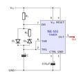
IC 555 timer
-
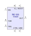
IC 555
https://tex.stackexchange.com/questions/64801/display-ics-with-circuitikz
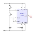
IC 555 circuit
-
IC555 circuit.
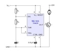
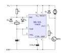
IC 555 with a NPN transistor
-
Added a transistor
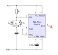
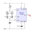
IC 555 and diodes
-
Addes some diodes
-
-
-
Motor and more stuff.
