DIY Cooking Temperature Meter
NTC probe
The resistance by measuring it using a multimeter at room temperature is about R=95 kΩ, so we may assume that the probe's resistance is 100 kΩ, which is a common value. At T=100 °C the resistance is about 6 kΩ.
Connect: 5V - R_0 - A0 - Probe - GND
Easy calibration points: Ice water (0 °C) and boiling water (100 °C).
The Beta Equation or Steinhart–Hart equation. Beta which gives
Thus, we have
- K
- K
and
A Beta value of about 3980 K is very common. Commercial NTC thermistors often have β values between 3400 K and 4300 K, with 3950 K being one of the most common nominal values. Many NTCs are specified as 10 kΩ @ 25 °C or 100 kΩ @ 25 °C. Yours is about 96 kΩ @ 23 °C, which corresponds to roughly 84–87 kΩ @ 25 °C. That's not a standard catalog value, but it's entirely plausible for a custom or OEM part.
Voltage divider: Choose the divider resistor approximately equal to the thermistor resistance at the middle of the temperature range of interest.
| Temp [°C] | R [kΩ] | ADC fraction |
|---|---|---|
| 60 | 24.7 | 0.943 |
| 100 | 6 | 0.800 |
| 150 | 1.69 | 0.530 |
| 200 | 0.59 | 0.282 |
| 250 | 0.24 | 0.136 |
The optimal fixed resistor would be . 1.5 kΩ, 0.1% metal film if possible (or 1% if that's what you have).
A single β model can deviate significantly at the extremes; a 3-point Steinhart–Hart calibration would give you a much better temperature conversion over −10…250 °C.
The Steinhart and Hart Equation is an empirical expression (which omits the term by emprical fitting.
where
- is the temperature in Kelvins
- is the resistance measured
- and are the coeffiecients. Because there are three coeffients, we need to have at least three measuring points.
See thinksrs.com/downloads/programs/therm%20calc/ntccalibrator/ntccalculator.html
The original ESP32 ADC isn't particularly linear/accurate over its entire range. Espressif recommends, for the original ESP32, approximately 150–2450 mV as the useful range with the highest attenuation setting (at 11 dB attenuation). Calibration is also important because the actual ADC reference varies between chips.
| T [°C] | R_NTC [kΩ] | ADC fraction 1.5 kΩ |
ADC fraction 4.7 kΩ |
ADC fraction 12 kΩ |
ADC fraction 20 kΩ |
ADC fraction 33 kΩ |
ADC fraction 47 kΩ |
ADC fraction 68 kΩ |
ADC fraction 100 kΩ |
|---|---|---|---|---|---|---|---|---|---|
| −10 | 596.3 | 0.9975 | 0.9922 | 0.9803 | 0.9675 | 0.9475 | 0.9269 | 0.8976 | 0.8563 |
| 0 | 343.1 | 0.9956 | 0.9865 | 0.9662 | 0.9449 | 0.9122 | 0.8795 | 0.8346 | 0.7743 |
| 50 | 35.35 | 0.9593 | 0.8826 | 0.7465 | 0.6386 | 0.5172 | 0.4293 | 0.3420 | 0.2613 |
| 100 | 6.73 | 0.8177 | 0.5888 | 0.3593 | 0.2519 | 0.1693 | 0.1253 | 0.0900 | 0.0629 |
| 150 | 1.897 | 0.5584 | 0.2876 | 0.1366 | 0.0866 | 0.0544 | 0.0388 | 0.0272 | 0.0186 |
| 200 | 0.701 | 0.3185 | 0.1298 | 0.0552 | 0.0339 | 0.0208 | 0.0146 | 0.0102 | 0.0070 |
| 250 | 0.312 | 0.1721 | 0.0622 | 0.0253 | 0.0154 | 0.00935 | 0.00658 | 0.00457 | 0.00311 |
Introduction
A simple (but updatable) cooking thermometer based on ESP32.
Functions
- Measure, log, display and save the temperature
- Send data using bt or create a local web server which shows the data.
- Allow taking timed photos (a photo at a given time) and show it on a (saved) temp log.
Material
-
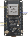 The pins. See also the svg file for editing purposes.
 -
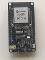 The ESP 32
 -
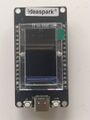 The front side of the ESP32 with the display
 -
 The battery shield from the front.
 -
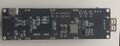 The battery shield from the back. The two leds1, L1 and L2 are in the middle of the board.
 -
 A sample file from the provider.


List
- ESP32: ideaspark® ESP32 Entwicklungsboard 1,14 Zoll 135x240 full color LCD-Display,CH340,WiFi+BL. ST7789 driver, I2C. CH340
- Display area: 14.864 × 24.912 mm2
- Panel size: 17.6 × 31.0 × 1.6 mm3
- Display current 20mA.
- Display ports. The used ports in ESP32 are D2(GPIO2), D4, D15, D18, D23, D32. Six pins totally (plus GND + VCC).
- VCC: VCC,
- GND: GND,
- D2(GPIO2): DC,
- D4: RST,
- D15: CS,
- D18: SCLK,
- D23: MOSI,
- D32: BLK.
- https://manuals.plus/asin/B0D7S7YQMC
- Note: WiFi and Display Coexistence (Important)
- Temperature probe; THERMOPRO copy (including TP20, TP17, and TP-16, TP-16S,TP08S, TP25, TP07, TP17H, TP27, TP06S, TP09, TP28). Max temp 380°C (716°F) with 3.5 mm stereo jack.
- Battery pack: Battery Shield V3 Raspberry Pi / Arduino / ESP32 - 1x 18650 (from FunDuino)
ESP32
-

-
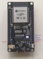 The LM1117 1.2V 800-mA, Low-Dropout Linear Regulator


On normal ESP32, the ADC1 pins are:
- GPIO32 (ADC1_CH4) - LCD (BLK)
- GPIO33 (ADC1_CH5)
- GPIO34 (ADC1_CH6)
- GPIO35 (ADC1_CH7)
- GPIO36 (ADC1_CH0)
- GPIO37 (ADC1_CH1 / often noted as not available on some boards)
- GPIO38 (ADC1_CH2)
- GPIO39 (ADC1_CH3)
Powering
- Never connect an external power source to the 3V3 pin while powering the ESP32 board via USB. This will cause damage to many boards!
- The VIN pin (sometimes labeled V5 or V5.0) can be used to power the ESP32 with an external regulated 5V DC power source
- you can power your ESP32 development board via the 3V3 pin.
See also
- https://esp32.com/viewtopic.php?t=40425
- https://forums.adafruit.com/viewtopic.php?t=208238&__cf_chl_f_tk=ttJRikxAdvhyUomGA3.7MIrCJ4_oN61zEkvdO0ihKmk-1783086585-1.0.1.1-YREDl6f36g.Q3yAgKoz6mc9s7QVpSaxWy4SarKdrx2Q
Battery Pack
No reverse voltage protection!
The charging voltage is 4.2 V and the charging current is 500 mA. Note the on/off switch, when plugging or unplugging the lipo battery, the On/OFF switch only switches the USB port. The 3 x 3 V and 3 x 5 V solder pins cannot be switched on and off by this switch
Deep discharge protection
The charging process on the module is indicated by a LED. Red means that the battery is charging and green signifies that charging is complete.
The battery shield connec
Programming
- Show the temperature log.
- Create a wifi and a local webserver
https://github.com/ImpulseAdventure/GUIslice https://blog.kamlatech.in/live-plot-sensor-data-on-tft-display
LVGL graphical library


