Quantum Gates
Introduction
Import the modules
from qiskit import QuantumCircuit, execute, Aer
from qiskit.visualization import plot_histogram, plot_bloch_vector
Plot the quantum circuit </syntaxhighlight> qc.draw('mpl') </syntaxhighlight>
Plot the results
backend = Aer.get_backend('statevector_simulator') # Tell Qiskit how to simulate our circuit
qc.measure_all()
qc.draw()
result = execute(qc,backend).result()
counts = result.get_counts()
plot_histogram(counts)
Quantum Gates of One Qubit
There are only two reversible gates, also identity (return the input unchanged) and NOT (return the opposite of the input), but neither is universal.
Identity gate.
Pauli X gate.
Pauli Y gate
Pauli Z gate
R gate
S gate or gate
T gate
U1 gate:
U2 gate:
qc = QuantumCircuit(1)
qc.x(0)
#qc.y(0) # Y-gate on qubit 0
#qc.z(0) # Z-gate on qubit 0
#qc.rz(pi/4, 0)
#qc.s(0)   # Apply S-gate to qubit 0
#qc.sdg(0) # Apply Sdg-gate to qubit 0
qc.t(0)   # Apply T-gate to qubit 0
qc.tdg(0) # Apply Tdg-gate to qubit 0

qc.draw('mpl')
# Let's see the result
backend = Aer.get_backend('statevector_simulator')
out = execute(qc,backend).result().get_statevector()
plot_bloch_multivector(out)
Two Qubit Quantum Gates
The reversibel gates are eg. identity, or CNOT.
Eg. .
backend = Aer.get_backend('unitary_simulator')
unitary = execute(qc,backend).result().get_unitary()
#
# In Jupyter Notebooks we can display this nicely using Latex.
# If not using Jupyter Notebooks you may need to remove the
# array_to_latex function and use print(unitary) instead.
from qiskit_textbook.tools import array_to_latex
array_to_latex(unitary, pretext="\\text{Circuit = }\n")
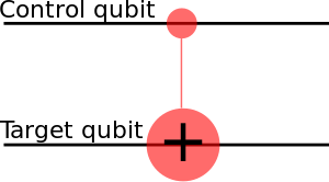
Eg. CNOT is a conditional gate that performs an X-gate on the second qubit, if the state of the first qubit (control) is . . This matrix swaps the amplitudes of |01⟩ and |11⟩ in the statevector. .
CNOT if a control qubit is on the superposition:
, which is Bell State. Entanglement, but no-communication theorem.
. Unchanged.
.
. Affects the state of the control qubit, only.
qc = QuantumCircuit(2)
# Apply H-gate to the first:
qc.h(0)
# Apply a CNOT:
qc.cx(0,1)
qc.draw('mpl')
#
# Let's see the result:
backend = Aer.get_backend('statevector_simulator')
final_state = execute(qc,backend).result().get_statevector()
# Print the statevector neatly:
array_to_latex(final_state, pretext="\\text{Statevector = }")
#
results = execute(qc,backend).result().get_counts()
plot_histogram(results)
Any controlled quantum gate is and in Qiskit formalism is written in matrix as
Controlled-Z. Because and we can write
qc = QuantumCircuit(2)
# also a controlled-Z
qc.h(t)
qc.cx(c,t)
qc.h(t)
qc.draw('mpl')
Controlled-Y is
qc = QuantumCircuit(2)
# a controlled-Y
qc.sdg(t)
qc.cx(c,t)
qc.s(t)
qc.draw('mpl')
or Controlled-H is
qc = QuantumCircuit(2)
# a controlled-H
qc.ry(pi/4,t)
qc.cx(c,t)
qc.ry(-pi/4,t)
qc.draw('mpl')
Swap gate
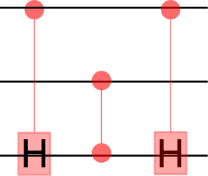
An arbitrary controlled-controlled-U for any single-qubit rotation U. We need and
#The controls are qubits a and b, and the target is qubit t.
#Subroutines cu1(theta,c,t) and cu1(-theta,c,t) need to be defined
qc = QuantumCircuit(3)
qc.cu1(theta,b,t)
qc.cx(a,b)
qc.cu1(-theta,b,t)
qc.cx(a,b)
qc.cu1(theta,a,t)
qc.draw('mpl')
Three Qubits

For universal computations we need more qubits. Eg. the AND gate is not reversible, and thus we need eg. Toffoli (CCNOT) gate.
Toffoli gate performs on target qubit if both control cubits are set to state .
qc = QuantumCircuit(3)
a = 0
b = 1
t = 2
# Toffoli with control qubits a and b and target t
qc.ccx(a,b,t)
qc.draw()
Toffoli using CNOTs uses fewer gates.
qc = QuantumCircuit(3)
qc.ch(a,t)
qc.cz(b,t)
qc.ch(a,t)
qc.draw()
AND gate is Toffoli gate with . . .

gives the reversible NAND
NAND gate is


