High frequency transmission lines
Introduction
Teoriaa: Systeemi
Antenn system.
Lähetin, johto, antenni, jne. https://www.antenna-theory.com/tutorial/txline/transmissionline.php
Transmission line
-
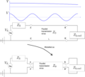
The (long) transmission line is modeled as Failed to parse (SVG (MathML can be enabled via browser plugin): Invalid response ("Math extension cannot connect to Restbase.") from server "https://wikimedia.org/api/rest_v1/":): {\displaystyle Z_0} . If the frequency (wavelength) of the source is too large (small) compared to dimensions of the system, it need to be considered in more detailed. See also the svg file.
-
The physical realizations of the transmission lines are usually coaxial cables, twisted cables or twin lead cables.
-

The system is analyzed as being differential short pieces. The conductance Failed to parse (SVG (MathML can be enabled via browser plugin): Invalid response ("Math extension cannot connect to Restbase.") from server "https://wikimedia.org/api/rest_v1/":): {\displaystyle G} is the conductance between the two wires, which exists because of the high frequency.


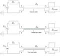
Transmission line
- Coaxial cable
- Two-wire cable
- Microstrip line
- . . .
If a transmission line has a length greater than about 10% of a wavelength, then the line length will noticeably affect the circuit's impedance. The solutions to the above equations is the sum of forward and backward traveling (reflected) waves: Failed to parse (SVG (MathML can be enabled via browser plugin): Invalid response ("Math extension cannot connect to Restbase.") from server "https://wikimedia.org/api/rest_v1/":): {\displaystyle v(z,t) = v^+ e^{-\alpha z} e^{\imath( \omega t - \gamma z )} + v^- e^{\alpha z} e^{\imath (\omega t +\gamma z) } } and if we assume that Failed to parse (SVG (MathML can be enabled via browser plugin): Invalid response ("Math extension cannot connect to Restbase.") from server "https://wikimedia.org/api/rest_v1/":): {\displaystyle \alpha=0} we have the telegraphers equations https://en.wikipedia.org/wiki/Telegrapher's_equations
Failed to parse (SVG (MathML can be enabled via browser plugin): Invalid response ("Math extension cannot connect to Restbase.") from server "https://wikimedia.org/api/rest_v1/":): {\displaystyle v(z,t) = v^+ e^{\imath (\omega t - \gamma z)} + v^- e^{\imath (\omega t +\gamma z)} } and a similar for Failed to parse (SVG (MathML can be enabled via browser plugin): Invalid response ("Math extension cannot connect to Restbase.") from server "https://wikimedia.org/api/rest_v1/":): {\displaystyle i=i(z,t)} . If we replace $i$ by Ohm law, we get
Failed to parse (SVG (MathML can be enabled via browser plugin): Invalid response ("Math extension cannot connect to Restbase.") from server "https://wikimedia.org/api/rest_v1/":): {\displaystyle i(z,t) = \frac{v^+}{Z_0} e^{\imath (\omega t - \gamma z) } + \frac{v^-}{Z_0} e^{\imath (\omega t +\gamma z)} = \frac{v^+}{Z_0} e^{\imath (\omega t - \gamma z)} \left( 1 - \frac{v^-}{v^+}e^{\imath(2\gamma z)} \right) }
The fraction Failed to parse (SVG (MathML can be enabled via browser plugin): Invalid response ("Math extension cannot connect to Restbase.") from server "https://wikimedia.org/api/rest_v1/":): {\displaystyle \frac{v^-}{v^+}} is called reflection coefficient Failed to parse (SVG (MathML can be enabled via browser plugin): Invalid response ("Math extension cannot connect to Restbase.") from server "https://wikimedia.org/api/rest_v1/":): {\displaystyle \Gamma}
Failed to parse (SVG (MathML can be enabled via browser plugin): Invalid response ("Math extension cannot connect to Restbase.") from server "https://wikimedia.org/api/rest_v1/":): {\displaystyle \frac{v^-}{v^+} = \Gamma e^{\imath \phi_z} = \frac{Z_L - Z_0}{Z_L + Z_0}}
which gives

The characteristic impedance is
Thus we have Failed to parse (SVG (MathML can be enabled via browser plugin): Invalid response ("Math extension cannot connect to Restbase.") from server "https://wikimedia.org/api/rest_v1/":): {\displaystyle \frac{d^2 v}{dL^2} = \gamma^2 v } and similar for the current. The constant Failed to parse (SVG (MathML can be enabled via browser plugin): Invalid response ("Math extension cannot connect to Restbase.") from server "https://wikimedia.org/api/rest_v1/":): {\displaystyle \gamma^2 = (R+\imath \omega L)(G+\imath \omega C)} .
Failed to parse (SVG (MathML can be enabled via browser plugin): Invalid response ("Math extension cannot connect to Restbase.") from server "https://wikimedia.org/api/rest_v1/":): {\displaystyle Z_0 = \frac{v^+}{i^+} = - \frac{v^-}{i^-} = \sqrt{ \frac{R' + \imath \omega L'}{G' + \imath \omega C'}} }
For lossless line Failed to parse (SVG (MathML can be enabled via browser plugin): Invalid response ("Math extension cannot connect to Restbase.") from server "https://wikimedia.org/api/rest_v1/":): {\displaystyle R' = G' = 0} and for distortionless line Failed to parse (SVG (MathML can be enabled via browser plugin): Invalid response ("Math extension cannot connect to Restbase.") from server "https://wikimedia.org/api/rest_v1/":): {\displaystyle R'/L' = G'/C'} . The voltage reflection coefficient Failed to parse (SVG (MathML can be enabled via browser plugin): Invalid response ("Math extension cannot connect to Restbase.") from server "https://wikimedia.org/api/rest_v1/":): {\displaystyle \Gamma}
Failed to parse (SVG (MathML can be enabled via browser plugin): Invalid response ("Math extension cannot connect to Restbase.") from server "https://wikimedia.org/api/rest_v1/":): {\displaystyle \Gamma = \frac{v^-}{v^+} = - \frac{i^-}{i^+} = \frac{Z_L - Z_0}{Z_L + Z_0} } where Failed to parse (SVG (MathML can be enabled via browser plugin): Invalid response ("Math extension cannot connect to Restbase.") from server "https://wikimedia.org/api/rest_v1/":): {\displaystyle Z_0} is the characteristic impedance of transient line, and Failed to parse (SVG (MathML can be enabled via browser plugin): Invalid response ("Math extension cannot connect to Restbase.") from server "https://wikimedia.org/api/rest_v1/":): {\displaystyle Z_L} is the impedance of load (antenna). If Failed to parse (SVG (MathML can be enabled via browser plugin): Invalid response ("Math extension cannot connect to Restbase.") from server "https://wikimedia.org/api/rest_v1/":): {\displaystyle Z_L= Z_0} , then the line is perfectly matched, and there is no mismatch loss and all power is transferred to the load (antenna).
- An open circuit: Failed to parse (SVG (MathML can be enabled via browser plugin): Invalid response ("Math extension cannot connect to Restbase.") from server "https://wikimedia.org/api/rest_v1/":): {\displaystyle Z_L = \infty} and Failed to parse (SVG (MathML can be enabled via browser plugin): Invalid response ("Math extension cannot connect to Restbase.") from server "https://wikimedia.org/api/rest_v1/":): {\displaystyle \Gamma = +1} .
- A short circuit: Failed to parse (SVG (MathML can be enabled via browser plugin): Invalid response ("Math extension cannot connect to Restbase.") from server "https://wikimedia.org/api/rest_v1/":): {\displaystyle Z_L = 0} and Failed to parse (SVG (MathML can be enabled via browser plugin): Invalid response ("Math extension cannot connect to Restbase.") from server "https://wikimedia.org/api/rest_v1/":): {\displaystyle \Gamma = -1} , and a phase reversal of the reflected voltage wave.
- A matched load: Failed to parse (SVG (MathML can be enabled via browser plugin): Invalid response ("Math extension cannot connect to Restbase.") from server "https://wikimedia.org/api/rest_v1/":): {\displaystyle Z_L = Z_0} , and Failed to parse (SVG (MathML can be enabled via browser plugin): Invalid response ("Math extension cannot connect to Restbase.") from server "https://wikimedia.org/api/rest_v1/":): {\displaystyle \Gamma = 0} and no reflections.
The voltage standing wave ratio or VSWR
Failed to parse (SVG (MathML can be enabled via browser plugin): Invalid response ("Math extension cannot connect to Restbase.") from server "https://wikimedia.org/api/rest_v1/":): {\displaystyle \text{VSWR} = \frac{|V|_\text{max}}{||V|_\text{min}|} = \frac{1 + |\Gamma|}{1 - |\Gamma|} }
Siirtolinja (transmission line). Impedanssi. Koaksaalikaapelin impedanssi muodostuu sen kapasitiivisestä rakenteesta. Ei juuri resistiivistä häviötä (impedanssia) https://electronics.stackexchange.com/questions/543100/derivation-of-resistance-of-coaxial-cable. Koaksaalikaapelin εr
- 76.7 Ω
- 30 Ω
- The impedance of a centre-fed dipole antenna in free space is 73 Ω, so 75 Ω coax is commonly used for connecting shortwave antennas to receivers.
- Sometimes 300 Ω folded dipole antenna => 4:1 balun transformer is used.
twin-lead transmission lines: the characteristic impedance of is roughly 300 Ω.
Feeding length.
Skin Effect
The skin effect Failed to parse (SVG (MathML can be enabled via browser plugin): Invalid response ("Math extension cannot connect to Restbase.") from server "https://wikimedia.org/api/rest_v1/":): {\displaystyle \delta} . The higher the frequency, the more the currents are confined to the surface.
Balun
Velocity factor
| Velocity factor | Line type |
|---|---|
| 0.95 | Ladder line |
| 0.82 | Twin-lead |
| 0.79 | coaxial cable (foam dielectric) |
| 0.75 | RG-6 and RG-8 coaxial (thick) |
| 0.66 | RG-58 and RG-59 coaxial (thin) |