TF03 Lidar and Arduino: Difference between revisions
| Line 263: | Line 263: | ||
=== PySerial === | === PySerial === | ||
Note that < | Note that <code>Readline</code> is very slow, use own method instead: https://stackoverflow.com/questions/29557353/how-can-i-improve-pyserial-read-speed | ||
Revision as of 18:00, 17 February 2024
Introduction
Long Manual https://acroname.com/sites/default/files/assets/tf03_product_manual_v0.4_en.pdf
TF (ToF; Time of Flight). https://www.sparkfun.com/products/19421
- Range ~100 m
- Resolution ~0.01 m/ Accuracy 0.1 m.
- Frame rate 1Hz - 1000 Hz
- wavelength: 905 nm. Laser class 1 (IEC 60825)
- Angle 0.5 deg; Spot size @100 m 28x28 cm2.
- Current ˝200 mA. Power ~1W
- Dimensions 44x43x32 mm3.
- Weight 77g
- IP67
- Mounting holes for M3 screws
- Connector: Molex 1.25 or Molex SD-51021-007 (1.25 W/B) 7 pin or mh1.25-7p. Pin to pin pitch is 1.25 mm. Identity electrical connectors: https://core-electronics.com.au/guides/Identify-Electrical-Connectors/#Molex
See more
- https://cdn.sparkfun.com/assets/2/c/5/6/0/Benewake_10152020_TF03_100-1954064.pdf
- https://cdn.sparkfun.com/assets/4/e/5/b/5/PM-15180.pdf
Need to measure angle. Use an accelerometer
Note the laser safety. Check whether the power supply is working properly, and whether the voltage level is kept within the range of the rated input voltage. If the power supply is normal, the TF03 lens will display a faint red light.
| No | Color | Standard: Pin | Standard: Function | RS485: PIN | RS485: Function |
|---|---|---|---|---|---|
| 1 | Red | Vcc | Power | Vcc | Power |
| 2 | White | CAN_L | CAN_L | RS485-B/RS232-RX | Receive |
| 3 | Green | CAN_H | CAN_H | RS485-B/RS232-TX | Transport |
| 4 | |||||
| 5 | Blue | UART_RX | Receive | UART_RX | Receive |
| 6 | Brown | UART_TX | Transport | UART_TX | Transport |
| 7 | Black | GND | Ground | GND | Ground |
The standard version of TF03 supports both, UART and CAN communication interface. The default interface is UART. The CAN mode can be set by sending command, but two interfaces cannot output simultaneously.
The default TX/RX pins on an Arduino board are the D0(RX) and D1(TX) pins.
| Data bit | Definition | Description |
|---|---|---|
| Byte0 | Frame Header | 0x59 |
| Byte1 | Frame Header | 0x59 |
| Byte2 | DIST_L | DIST low 8-bits |
| Byte3 | DIST_H | DIST high 8-bits |
| Byte4 | Reserved | (Signal strength L) |
| Byte5 | Reserved | (Signal strength H) |
| Byte6 | Reserved | |
| Byte7 | Reserved | |
| Byte8 | Checksum | Checksum = Byte0 + Byte2 + ... 0 Byte7 |
Signal strength is between 0 and 3500. The threshold is 40. Between 40 and 1200 distance is more reliable. If there is a high reflectivity object, strength will be over 1500.
2 Byte Conversion to decimal
The two bytes (high and low) need to be concatenated and displayed as a decimal number.
- Byte[2] = DIST_L, low 8 bits
- Byte[3] = DIST_H, high 8 bits
For example, 10101010 01010101 gives 43605.
We need to left shift high bits by 8 bits and union the two numbers by using eg or operation
uint8_t = dist_l;
uint8_t = dist_h;
uint16_t = dist;

dist = dist_h;
dist <<= 8;
dist = dist | dist_l
Serial.print( dist, HEX )
Serial.print( dist, BIN )
The left shift moves bits to the left and pads from the right with zeroes. Eg, 0000 1110 << 2 will be 0011 1000.
Lidar & Arduino
Connections
- Arduino: D0 (RX), TF03: 6 (Brown, UART TX)
- Arduino: D1 (TX), TF03: 5 (Blue, UART RX)
The serial port version of TF03 adopts UART-LVTTL interface, and the output level is LVTTL level (0-3.3V).
Lidar Voltage: 5 - 24 V (https://cdn.sparkfun.com/assets/2/c/5/6/0/Benewake_10152020_TF03_100-1954064.pdf); Current 150 mA @ 5V, 80 mA @ 12V, 50 mA @ 24 V. Power consumption: 1 W.
Communication protocol UART
- Baud rate 115200
- Data bit 8
- Stop bit 1
- Checksum bit None
void setup(){
  Serial.begin(115200);
}
void loop(){
  if (Serial.available() > 0){  // returns the number of bytes waiting in the buffer
    processInputByte(Serial.read());
  }
}
See also https://lastminuteengineers.com/tfmini-s-lidar-sensor-arduino-tutorial/
ProcessInputByte subroutine
This subroutine will take care of reading the bits.
void processInputByte(unsigned char inByte){
  if ( recvdByte < 2){
    if (inByte != start_signature[recvdByte]) {  // Check the headers; frame header
            recvdByte = 0;  // discard the packet
            return;
    }
  if ( recvdByte > 4 && recvdByte < 8){   //Do checks ???
  }
  } else if (recvdByte == 8) {  // check sum
        // TODO: Look at the datasheet to see how to control that
        // the checksum is correct. Discard the packet if it is not.
  }

  // All correct so far, we can buffer the incoming byte.
  packet[recvdByte++] = inByte;

  // If we have a complete packet now, handle it.
  if (recvdByte == 9 ) {
      dist_l = char(packet[2]);
      dist_h = char(packet[3]);

      dist = dist_h;
      dist <<= 8;
      dist = dist | dist_l;
      Serial.println( dist, DEC );

      recvdByte = 0;  // reset for the next packet
      dataLength = 0;
  }
}
That's all.
Reading Digital Pins

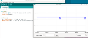
While reading the digital pin, we get some data. However, it looks rather similar and boring.
int val = 0;

void setup() {
  pinMode(1, INPUT);  // sets the digital pin 13 as output
  Serial.begin(115200);
}

void loop() {
  val = digitalRead(1);   // read the input pin
  Serial.println(val);  // sets the LED to the button's value
}
TX/RX pins
Use Digital 0, but uploading fails. Need to unplug the wire, upload the code and plug the wire ; gives
| Frame Header | Frame Header | Dist_L | Dist_H | Reserved | Reserved | Reserved | Reserved | Checksum |
|---|---|---|---|---|---|---|---|---|
| 59 | 59 | 35 | 0 | 37 | 0 | 0 | 0 | 1E |
where
- Dist_L is distance low 8 bits
- Dist_H is distance hight 8 bits
- Checksum is Low 8 bits of checksum; checksum = Byte0 + Byte2 + ... + Byte7
Software Serial

However, according https://arduino.stackexchange.com/questions/91215/how-to-read-and-parse-uart-data-from-human-presence-radar-sensor Software Serial should not be used:
- against using SoftwareSerial, especially at this high baud rates: it is a recipe for problems.
- Connect the sensor's TX to the Arduino RX, and you will be able to read the sensor data with Serial.read().
- Do not connect the sensor's RX, and you will be able to Serial.print() to the serial monitor without disturbing the sensor.
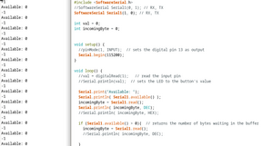
#include <SoftwareSerial.h>
//SoftwareSerial Serial1(0, 1); // RX, TX
SoftwareSerial Serial1(1, 0); // RX, TX
int val = 0;
int incomingByte = 0;

void setup() {
  Serial.begin(115200);
}
void loop() {
  Serial.print("Available: ");
  Serial.println( Serial1.available() );
  incomingByte = Serial1.read();
  Serial.println( incomingByte, HEX);

  if (Serial1.available() > 0){  // returns the number of bytes waiting in the buffer
    incomingByte = Serial1.read();
    //Serial.println( incomingByte, DEC);
  }
}
And this gives bad results, see the image. The program and results are shown. The results are not very convincing. However, in the beginning, it gives some data.
References
See also https://ardupilot.org/copter/docs/common-benewake-tf02-lidar.html
and Benewake TF02 manual.
Data into PC
Some methods:
- Browser: Potree https://github.com/potree/potree/ needs its own dataformat, so not probably real time visualization.
- Python: Point Cloud Open 3D https://www.open3d.org/docs/release/tutorial/geometry/pointcloud.html . Real time rendering works https://stackoverflow.com/questions/65774814/adding-new-points-to-point-cloud-in-real-time-open3d
PySerial
Note that Readline is very slow, use own method instead: https://stackoverflow.com/questions/29557353/how-can-i-improve-pyserial-read-speed