DIY Cooking Temperature Meter: Difference between revisions
| Line 30: | Line 30: | ||
** https://nerd-corner.com/review-battery-shield-v3-diy-powerbank-with-lipo-18650/ | ** https://nerd-corner.com/review-battery-shield-v3-diy-powerbank-with-lipo-18650/ | ||
** https://www.youtube.com/watch?v=T70mBHeIOZA | ** https://www.youtube.com/watch?v=T70mBHeIOZA | ||
=== ESP32 === | |||
The VIN pin (sometimes labeled V5 or V5.0) can be used to power the ESP32 with an external regulated 5V DC power source | |||
=== Battery Pack === | === Battery Pack === | ||
Revision as of 15:13, 3 July 2026
Introduction
A simple (but updatable) cooking thermometer based on ESP32.
Functions
- Measure, log, display and save the temperature
- Send data using bt or create a local web server which shows the data.
- Allow taking timed photos (a photo at a given time) and show it on a (saved) temp log.
Material
-
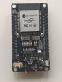
The ESP 32
-
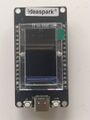
The front side of the ESP32 with the display
-

The battery shield from the front.
-
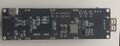
The battery shield from the back. The two leds1, L1 and L2 are in the middle of the board.
-

A sample file from the provider.


- ESP32: ideaspark® ESP32 Entwicklungsboard 1,14 Zoll 135x240 full color LCD-Display,CH340,WiFi+BL. ST7789 driver, I2C. CH340
- Display area: 14.864 × 24.912 mm2
- Panel size: 17.6 × 31.0 × 1.6 mm3
- Display current 20mA.
- Display ports: VCC: VCC, GND: GND, D2(GPIO2): DC, D4: RST, D15: CS, D18: SCLK, D23: MOSI, D32: BLK.
- Temperature probe; THERMOPRO copy (including TP20, TP17, and TP-16, TP-16S,TP08S, TP25, TP07, TP17H, TP27, TP06S, TP09, TP28). Max temp 380°C (716°F) with 3.5 mm stereo jack.
- Battery pack: Battery Shield V3 Raspberry Pi / Arduino / ESP32 - 1x 18650 (from FunDuino)
ESP32
The VIN pin (sometimes labeled V5 or V5.0) can be used to power the ESP32 with an external regulated 5V DC power source
Battery Pack
No reverse voltage protection!
The charging voltage is 4.2 V and the charging current is 500 mA. Note the on/off switch, when plugging or unplugging the lipo battery, the On/OFF switch only switches the USB port. The 3 x 3 V and 3 x 5 V solder pins cannot be switched on and off by this switch
Deep discharge protection
The charging process on the module is indicated by a LED. Red means that the battery is charging and green signifies that charging is complete.
The battery shield connec


