DIY Cooking Temperature Meter: Difference between revisions
(→ESP32) |
|||
| (16 intermediate revisions by the same user not shown) | |||
| Line 14: | Line 14: | ||
Esp32 display front.jpg|The front side of the ESP32 with the display | Esp32 display front.jpg|The front side of the ESP32 with the display | ||
Batteryshieldv3 front.jpg|The battery shield from the front. | Batteryshieldv3 front.jpg|The battery shield from the front. | ||
Batteryshieldv3 back.jpg|The battery shield from the back. | Batteryshieldv3 back.jpg|The battery shield from the back. The two leds1, L1 and L2 are in the middle of the board. | ||
DIY cooking temp samplecode.png|A sample file from the provider. | DIY cooking temp samplecode.png|A sample file from the provider. | ||
</gallery> | </gallery> | ||
=== List === | |||
* ESP32: ideaspark® ESP32 Entwicklungsboard 1,14 Zoll 135x240 full color LCD-Display,CH340,WiFi+BL. ST7789 driver, I2C. CH340 | * ESP32: ideaspark® ESP32 Entwicklungsboard 1,14 Zoll 135x240 full color LCD-Display,CH340,WiFi+BL. ST7789 driver, I2C. CH340 | ||
| Line 24: | Line 25: | ||
** Display current 20mA. | ** Display current 20mA. | ||
** Display ports: VCC: VCC, GND: GND, D2(GPIO2): DC, D4: RST, D15: CS, D18: SCLK, D23: MOSI, D32: BLK. | ** Display ports: VCC: VCC, GND: GND, D2(GPIO2): DC, D4: RST, D15: CS, D18: SCLK, D23: MOSI, D32: BLK. | ||
** https://manuals.plus/asin/B0D6QXC813 | |||
*** Note: WiFi and Display Coexistence (Important) | |||
* Temperature probe; THERMOPRO copy (including TP20, TP17, and TP-16, TP-16S,TP08S, TP25, TP07, TP17H, TP27, TP06S, TP09, TP28). Max temp 380°C (716°F) with 3.5 mm stereo jack. | * Temperature probe; THERMOPRO copy (including TP20, TP17, and TP-16, TP-16S,TP08S, TP25, TP07, TP17H, TP27, TP06S, TP09, TP28). Max temp 380°C (716°F) with 3.5 mm stereo jack. | ||
* Battery pack: Battery Shield V3 Raspberry Pi / Arduino / ESP32 - 1x 18650 (from FunDuino) | * Battery pack: Battery Shield V3 Raspberry Pi / Arduino / ESP32 - 1x 18650 (from FunDuino) | ||
** https://nerd-corner.com/download/1039/?tmstv=1755621929 | |||
** Breakdown of the components: https://www.edn.com/battery-shield/ | ** Breakdown of the components: https://www.edn.com/battery-shield/ | ||
** https://nerd-corner.com/review-battery-shield-v3-diy-powerbank-with-lipo-18650/ | ** https://nerd-corner.com/review-battery-shield-v3-diy-powerbank-with-lipo-18650/ | ||
** https://www.youtube.com/watch?v=T70mBHeIOZA | ** https://www.youtube.com/watch?v=T70mBHeIOZA | ||
=== ESP32 === | |||
<gallery> | |||
Esp32 display back VIN.jpg | |||
Esp32 display back regulator.jpg| The LM1117 1.2V 800-mA, Low-Dropout Linear Regulator | |||
</gallery> | |||
Powering | |||
* Never connect an external power source to the 3V3 pin while powering the ESP32 board via USB. This will cause damage to many boards! | |||
* The VIN pin (sometimes labeled V5 or V5.0) can be used to power the ESP32 with an external regulated 5V DC power source | |||
* you can power your ESP32 development board via the 3V3 pin. | |||
See also | |||
* https://esp32.com/viewtopic.php?t=40425 | |||
* https://forums.adafruit.com/viewtopic.php?t=208238&__cf_chl_f_tk=ttJRikxAdvhyUomGA3.7MIrCJ4_oN61zEkvdO0ihKmk-1783086585-1.0.1.1-YREDl6f36g.Q3yAgKoz6mc9s7QVpSaxWy4SarKdrx2Q | |||
=== Battery Pack === | |||
No reverse voltage protection! | |||
The charging voltage is 4.2 V and the charging current is 500 mA. Note the on/off switch, when plugging or unplugging the lipo battery, the On/OFF switch only switches the USB port. The 3 x 3 V and 3 x 5 V solder pins cannot be switched on and off by this switch | |||
Deep discharge protection | |||
The charging process on the module is indicated by a LED. Red means that the battery is charging and green signifies that charging is complete. | |||
The battery shield connec | The battery shield connec | ||
== Programming == | |||
* Show the temperature log. | |||
* Create a wifi and a local webserver | |||
https://github.com/ImpulseAdventure/GUIslice https://blog.kamlatech.in/live-plot-sensor-data-on-tft-display | |||
LVGL graphical library | |||
https://www.youtube.com/watch?v=qZ055lfGQKA | |||
Latest revision as of 17:15, 3 July 2026
Introduction
A simple (but updatable) cooking thermometer based on ESP32.
Functions
- Measure, log, display and save the temperature
- Send data using bt or create a local web server which shows the data.
- Allow taking timed photos (a photo at a given time) and show it on a (saved) temp log.
Material
-
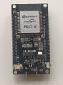
The ESP 32
-
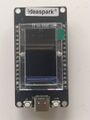
The front side of the ESP32 with the display
-

The battery shield from the front.
-
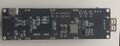
The battery shield from the back. The two leds1, L1 and L2 are in the middle of the board.
-

A sample file from the provider.


List
- ESP32: ideaspark® ESP32 Entwicklungsboard 1,14 Zoll 135x240 full color LCD-Display,CH340,WiFi+BL. ST7789 driver, I2C. CH340
- Display area: 14.864 × 24.912 mm2
- Panel size: 17.6 × 31.0 × 1.6 mm3
- Display current 20mA.
- Display ports: VCC: VCC, GND: GND, D2(GPIO2): DC, D4: RST, D15: CS, D18: SCLK, D23: MOSI, D32: BLK.
- https://manuals.plus/asin/B0D6QXC813
- Note: WiFi and Display Coexistence (Important)
- Temperature probe; THERMOPRO copy (including TP20, TP17, and TP-16, TP-16S,TP08S, TP25, TP07, TP17H, TP27, TP06S, TP09, TP28). Max temp 380°C (716°F) with 3.5 mm stereo jack.
- Battery pack: Battery Shield V3 Raspberry Pi / Arduino / ESP32 - 1x 18650 (from FunDuino)
ESP32
-

-
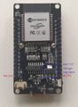
The LM1117 1.2V 800-mA, Low-Dropout Linear Regulator


Powering
- Never connect an external power source to the 3V3 pin while powering the ESP32 board via USB. This will cause damage to many boards!
- The VIN pin (sometimes labeled V5 or V5.0) can be used to power the ESP32 with an external regulated 5V DC power source
- you can power your ESP32 development board via the 3V3 pin.
See also
- https://esp32.com/viewtopic.php?t=40425
- https://forums.adafruit.com/viewtopic.php?t=208238&__cf_chl_f_tk=ttJRikxAdvhyUomGA3.7MIrCJ4_oN61zEkvdO0ihKmk-1783086585-1.0.1.1-YREDl6f36g.Q3yAgKoz6mc9s7QVpSaxWy4SarKdrx2Q
Battery Pack
No reverse voltage protection!
The charging voltage is 4.2 V and the charging current is 500 mA. Note the on/off switch, when plugging or unplugging the lipo battery, the On/OFF switch only switches the USB port. The 3 x 3 V and 3 x 5 V solder pins cannot be switched on and off by this switch
Deep discharge protection
The charging process on the module is indicated by a LED. Red means that the battery is charging and green signifies that charging is complete.
The battery shield connec
Programming
- Show the temperature log.
- Create a wifi and a local webserver
https://github.com/ImpulseAdventure/GUIslice https://blog.kamlatech.in/live-plot-sensor-data-on-tft-display
LVGL graphical library


