The color coded in resistors are difficult to read. Thus, we will use the ADC in Arduino and voltage dividing circuit to measure the resistances.
Theory: Voltage divider
Voltage divider is a simple circuit with two resistors, one known and other unknown.
Voltage divider is a simple circuit with two resistors, one known and other unknown. According to Kirchhoff voltage law, all potential in the circuit will be used. If we input +5V into a circuit, and the known resistor uses , the other has to be used. Also, we know that which gives the current in the circuit to be . Furthermore, this gives that .
The potential (voltage) can be read using Arduino's Analog to Digital Converter (ADC) in the analog input ports.
Theory: Arduino circuit
Voltage divider.
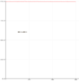
The input voltage is . The input to the A5 pin is called .
.
or similarly
which gives the same result.
Theory: Arduino program
and as a reference data.
and
and
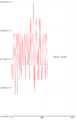
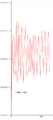
The simple program to show . Arduino has 10 bit analog to digital converter, thus there are different values for analog pins, such as .
intraw=0;floatR1=1000;//Known resistancefloatR2=0;//Unknown resistance, we have to measurevoidsetup(){Serial.begin(9600);}voidloop(){raw=analogRead(5);if(raw){R2=raw/(1024.0-raw)*R1;Serial.print("R2: ");Serial.println(R2);}}
The decimal in 1024.0 makes it to float, and thus the result will be float.
Note that the input voltage +5V cancels out, because and thus