Generate pwm using ic 555
Introduction
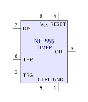
IC 555 is an astable multivibrator (oscillator).
Frequency: The ON time is defined by the time taken to its capacitor to charge to 2/3 (1/e??) level through pin7 resistor, and the OFF time is the discharging time of the capacitor through pin7, 1/3.
Theory

The resistance is much smaller than the resistance of the potentiometer, for example, 1K compared to 100K of the potentiometer. In that way we have 99% control over the charging and discharging resistance in the circuit.

The output of the 555 timer can source a current of 200mA to the load.
- Use MOSFET (eg TIP122 Darlington transistor; 5A) for driving the motor.
Method 1
The capacitor is charging through and but discharges only through using IC 555. Thus should be a potentiometer.

The F capacitor is to ensure that the CTRL and GND stays on the same voltage level. The CTRL pin of the 555 is to level out any fluctuations in the power supply voltage that might affect the operation.

![]()
Method 2: with diodes
555 internal design and theory
See https://www.electronicshub.org/555-timer-pwm/
and the internal circuit looks like below:
References
https://www.homemade-circuits.com/how-to-use-ic-555-for-generating-pwm/