DIY drum machine sequencer with samples
Introduction


Teensy based drum machine/ sequencer (groovebox?) with high quality samples
The knobs:
- Bpm
- Play/ record
- Free rhythm / on beat
- Track number selection
- Length: 8 / 16 beats
- number showing current step
- Drums; shown below.
- Display? showing the situation
Use potentiometer as Rotary selector switch.
The drums included (see https://en.wikipedia.org/wiki/List_of_percussion_instruments)
- Bass Drum https://samplefocus.com/samples/bass-drum-hit?search_id=199954966
- Bongo Drum
- Cajon Drum
- Castanets
- Conga Drums
- Cowbell https://samplefocus.com/samples/cowbell-f92f5f7b-5be6-44b7-bd5c-055dab612e55?search_id=199955024
- Cymbals https://samplefocus.com/samples/bright-soft-crash?search_id=199954863
- Djembe Drum
- Gongs
- Hi-hat
- Maracas
- Snare Drum https://samplefocus.com/samples/snare-drum-phonk-hit
- Steelpan https://samplefocus.com/samples/steel-pan-drum-15?search_id=199954909
- Tambourine
- Triangle
- Woodblock
Material
-
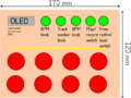
The plan. Note that also the svg version is available.

- 0.91" OLED Display module 128x32 px. I2C (SSD1306 driver). 36 x 12.5 (mm). Too small for my eyes.
- Teensy 4.1 - No ethernet
- 55 digital input/output pins, 35 PWM output pins
- 18 analog input pins
- 8 serial, 3 SPI, 3 I2C ports
- 3 CAN Bus (1 with CAN FD)
- Output 3.3V 250mA out
- Vin 3.6 V to 5.5V
- Audio Adapter board for Teensy 4.0 (Rev D) https://www.pjrc.com/store/teensy3_audio.html
- 8 x Mini LED Arcade buttons 24 mm. (The parallel ~1K resistors are built in. Power the LED from a microcontroller pin or direct from 5V (eg a USB) with 10mA draw. With 3.3V power, 2mA per button.) See arcade button wiring guide https://himuragames.com/led-arcade-buttons-wiring-guide/ Thus 250mA/2mA gives many.
- 3 x Illuminated Latching push button 16 mm
Wiring
Wiring the arcade buttons.
- use the internal pullup resistor, connect one side of the button to GND and the other side to a pin on the Teensy. Use pinMode(pin, INPUT_PULLUP); to enable the internal pullup resistor (an internal pull up resistor [~47kΩ] is enabled, to keep the signal HIGH by default.)
- Use Debouncing library: The high speed of the Teensy 4.1 makes it very sensitive to mechanical switch bounce. Use a library like Bounce2 for reliable button input.
Simple test program. Should use Bounce(pin, time); function.
const int buttonPin1 = 32;  // the number of the pushbutton pin
const int buttonPin2 = 31;  // the number of the pushbutton pin
const int buttonPin3 = 30;  // the number of the pushbutton pin
const int buttonPin4 = 29;  // the number of the pushbutton pin

void setup() {
  Serial.begin(9600);

  pinMode(buttonPin1, INPUT_PULLUP);
  pinMode(buttonPin2, INPUT_PULLUP);
  pinMode(buttonPin3, INPUT_PULLUP);
  pinMode(buttonPin4, INPUT_PULLUP);
}

void loop() {
  if ( digitalRead(buttonPin1) == LOW ){
    Serial.println("1");
  }
  if ( digitalRead(buttonPin2) == LOW ){
    Serial.println("2");
  }
  if ( digitalRead(buttonPin3) == LOW ){
    Serial.println("3");
  }
  if ( digitalRead(buttonPin4) == LOW ){
    Serial.println("4");
  }
}
Potentiometer
- Potentiometer + Pin to 3.3V
- Potentiometer - Pin to GND
- Potentiometer Data Pin
OLED Display module
- I2C (Normally a 4.7K pullup resistor is connected between each signal and power, but the weak internal pullup resistors may be sufficient for short wires to a single device.)
- SDA (18, Wire1 17, or 25)
- SCL (19, Wire1 16, or 24)
Audio Board, I2C
- SDA 18
- SCL 19
Teensy Pins
Teensy 4.1 has a total of 55 input/output signal pins, from which 42 are easily accessible when used with a solderless breadboard. In teensy 4.1, 35 PWM pin support and 18 analog pins are present.
The pins 23 - 32 and 33 - 42 are easily available.
- The 23 is 3.3V output. The potentiometer's other end should be there.
- Pins A0 - A17 (24, 25, 26, 27 and 38, 39, 40, 41) are analog input pins. See https://www.etechnophiles.com/teensy-4-1-pinout/
Teensy 4 Audio Library and Audio Board
Audio Board
https://www.pjrc.com/store/teensy3_audio.html
Audio Board is based on the SGTL5000 chip which in addition to ADC/DAC and amplifiers also offers some basic DSP functionality. The Adapter board has line input and output, mic input, and headphone output. Connect to Teensy using very short wires because of high-frequency master clock input (MCLK).
Audio Board connects to Teensy using 7 signals. The I2C pins SDA and SCL are used to control the chip and adjust parameters. Audio data uses I2S signals. DIN and DOUT and 3 clocks (LRCLK 44.1 kHZ, BCLK 1.41 or 2.82 MHZ and MCLK 11.29 MHz.
| Signal | Rev D, D2 (Teensy 4.x) | Required For | Function |
|---|---|---|---|
| MCLK | 23 (MCLK1) | Audio | Audio Master Clock, 11.29 MHz |
| BCLK | 21 (BCLK1) | Audio | Audio Bit Clock, 1.41 or 2.82 MHz |
| LRCLK | 20 (LRCLK1) | Audio | Audio Left/Right Clock, 44.1 kHz |
| DIN | 7 (OUT1A) | Audio Output | Audio Data from Teensy to Audio Shield. Goes to both headphone jack and Line-Out pins. |
| DOUT | 8 (IN1) | Audio Input | Audio Data from Audio Shield to Teensy. Comes from either Microphone or Line-In pins. |
| SCL | 19 | Audio Config | Control Clock (I2C) |
| SDA | 18 | Audio Config | Control Data (I2C) |
| SCK | 13 | Optional Data SD or MEM | Data Storage (SPI) Clock |
| MISO | 12 | Optional Data SD or MEM | Data Storage (SPI) from SD/MEM to Teensy |
| MOSI | 11 | Optional Data SD or MEM | Data Storage (SPI) from Teensy to SD/MEM |
| SDCS | 10 | Optional Data SD Card | Chip Select (SPI) for SD Card |
| MEMCS | 6 | Optional Data MEM Chip | Chip Select (SPI) for Memory Chip |
| Vol | 15 / A1 | Optional Knob | Volume Thumbwheel (analog signal) |
Play a sine wave
Test 1, almost from https://gist.github.com/mwicat/4c129fe835d58258688974d5e02ffb75
#include <Audio.h>

AudioSynthWaveformSine sineWave; // Create a sine wave object
AudioOutputAnalog output; // Create an analog output object
AudioConnection patchCord(sineWave, output);

void setup() {
  AudioMemory(8); // Allocate memory for audio processing
  sineWave.frequency(440); // Set frequency to 440 Hz (A4)
  sineWave.amplitude(0.5); // Set amplitude
}

void loop() {
  // The sine wave will continuously play
}
Test2 Sine/Square Wave Generator: https://github.com/jameskeaveney/Teensy-SineWaveGenerator/blob/master/SineGen.ino
Teensy 4 Signal Generator
DDS (Direct Digital Synthesis) For teensy 3.5 https://github.com/EmaMaker/SignalGenerator-Teensy/blob/master/README.md
Harmonic distortion https://kennypeng.com/2020/11/23/teensy_harmonic_distortion.html https://github.com/colonelwatch/teensy-harmonic-distortion
Teensy Dynamic Sound Effects Processor https://cdn.hackaday.io/files/1638357009516640/Final%20Project_Complete.pdf
Hackaday tutorial
The tutorial: https://hackaday.io/project/8292-microcontroller-audio-workshop-had-supercon-2015 and the pdf file from https://raw.githubusercontent.com/PaulStoffregen/AudioWorkshop2015/master/workshop.pdf
Playing a file from SD card. File → Examples → Audio → Tutorial → Part_1_03_Playing_Music. Also available below (slightly modified version) and at https://github.com/PaulStoffregen/Audio/blob/master/examples/WavFilePlayer/WavFilePlayer.ino
- Insert the Micro SD card from the card reader and into the Teensy Audio Shield before you upload the program. The music files are stored on this MicroSD card.
Three different audio outputs
- AudioOutputI2S audioOutput;
- AudioOutputSPDIF audioOutput;
- AudioOutputAnalog audioOutput;
See the memory function at MemoryAndCpuUsage example
The patchCord1(playWav1, 0, audioOutput, 0); connects the left output channel (channel 0) of the WAV file player (playWav1) to the left input channel (channel 0) of the audio output (audioOutput).
#include <Audio.h>
#include <Wire.h>
#include <SPI.h>
#include <SD.h>
#include <SerialFlash.h>

AudioPlaySdWav           playWav1;
AudioOutputI2S           audioOutput;

AudioConnection          patchCord1(playWav1, 0, audioOutput, 0);
AudioConnection          patchCord2(playWav1, 1, audioOutput, 1);
AudioControlSGTL5000     sgtl5000_1;

// Use these with the Teensy Audio Shield
#define SDCARD_CS_PIN    10
#define SDCARD_MOSI_PIN  7   // Teensy 4 ignores this, uses pin 11
#define SDCARD_SCK_PIN   14  // Teensy 4 ignores this, uses pin 13

void setup() {
  Serial.begin(9600);
  AudioMemory(8);

  sgtl5000_1.enable();
  sgtl5000_1.volume(0.5);

  SPI.setMOSI(SDCARD_MOSI_PIN);
  SPI.setSCK(SDCARD_SCK_PIN);
  if (!(SD.begin(SDCARD_CS_PIN))) {
    // stop here, but print a message repetitively
    while (1) {
      Serial.println("Unable to access the SD card");
      delay(500);
    }
  }
}

void playFile(const char *filename){
  Serial.print("Playing file: ");
  Serial.println(filename);

  playWav1.play(filename);

  delay(25);  // A brief delay for the library read WAV info

  // Simply wait for the file to finish playing.
  while (playWav1.isPlaying()) {
  }
}


void loop() {
  playFile("SDTEST1.WAV");  // filenames are always uppercase 8.3 format
  delay(500);
  playFile("SDTEST2.WAV");
  delay(500);
  playFile("SDTEST3.WAV");
  delay(500);
  playFile("SDTEST4.WAV");
  delay(1500);
}
Blink LED while Playing Music. File → Examples → Audio → Tutorial → Part_1_04_Blink_While_Playing
Use eg
elapsedMillis blinkTime;
. . .
 if (blinkTime < 250) {
    digitalWrite(LED_PIN, LOW);
  } else if (blinkTime < 500) {
    digitalWrite(LED_PIN, HIGH);
  } else {
    blinkTime = 0; // start blink cycle over again
  }
Do More While Playing Music.
File → Examples → Audio → Tutorial → Part_1_05_Do_More_While_Playing
- The potentiometer controls the volume immediately, regardless of status of the LED.
- The pushbuttons are read using the Bounce library
The GUI
Audio system design GUI https://www.pjrc.com/teensy/gui/ (page 9) From the main Arduino folder, navigate to these folders hardware / teensy / avr / libraries / Audio / gui. Inside the gui folder, open index.html
References
Teensy / Arduino/ ESP32 based drum machine/ sequencer with high quality samples. Use MIDI to transfer data from sequencer to synth. / Groovebox. References:
DIY Arduino Drum Synth + FREE SAMPLES! https://www.youtube.com/watch?v=xo-iN3tfE6o
- Simple, good starting point!
- https://github.com/NickCulbertson/Arduino-Audio-Projects
https://www.instructables.com/MIDI-Drum-Machine/
ARDUINO 8 STEP KEYBOARD SEQUENCER FOR SYNTHESIZERS https://www.youtube.com/watch?v=9oGlCfwCoCw
- https://www.lookmumnocomputer.com/projects/#/sequencer-keyboard
- CV patch cables (also called mini-jack patch cables, modular patch cables or Eurorack cables)
Drum trigger sequencer. How To Make Your Own Drum Sequencer DIY The BIG BUTTON https://www.youtube.com/watch?v=6ArDGcUqiWM
https://diyelectromusic.com/2021/06/23/arduino-mozzi-sample-drum-sequencer/
Doof machine
https://github.com/gavD/arduino-drum-machine
Mozzi https://sensorium.github.io/Mozzi/gallery/
The Bastl Microgranny https://www.instructables.com/Microgranny-Sampler-Completely-Home-built-not-a-Ki/
SnapBeat https://www.hackster.io/hiro-akihabara/snapbeat-the-simple-lo-fi-sampler-5a3222
https://www.youtube.com/watch?v=U5Q8chfMglE
https://www.youtube.com/watch?v=YeKsXck8LDY
- TOERN new version https://toern.live/
MOTHSYNTH https://www.mothsynth.com/
Samplotron https://hackaday.io/project/205253/components
Pushpin https://pushpin.kinga.dev/
Cosmic Loop https://github.com/kreiff/Cosmic_Loop
OpnBeat https://hackaday.io/project/190273-opnbeat-diy-lo-fi-sampler-with-isd1700-series
Launchpad https://github.com/pabolojo/DIY-Launchpad
Yorick https://bristol-communal-modular.github.io/yorick/?utm_source=chatgpt.com
Button test
//LEFT SIDE
const int buttonPin1 = 41;  // the number of the pushbutton pin
const int buttonPin2 = 40;  // the number of the pushbutton pin
const int buttonPin3 = 39;  // the number of the pushbutton pin
const int buttonPin4 = 38;  // the number of the pushbutton pin
const int buttonPin5 = 37;  // the number of the pushbutton pin
const int buttonPin6 = 36;  // the number of the pushbutton pin
const int buttonPin7 = 35;  // the number of the pushbutton pin
const int buttonPin8 = 34;  // the number of the pushbutton pin
//last is empty

//RIGHT SIDE
const int potentiometer1 = 24;  // ANALOG INPUT

const int togglePin1 = 25;  // the number of the pushbutton pin
const int togglePin2 = 26;  // the number of the pushbutton pin

void setup() {
  Serial.begin(9600);

  pinMode(buttonPin1, INPUT_PULLUP);
  pinMode(buttonPin2, INPUT_PULLUP);
  pinMode(buttonPin3, INPUT_PULLUP);
  pinMode(buttonPin4, INPUT_PULLUP);
  pinMode(buttonPin5, INPUT_PULLUP);
  pinMode(buttonPin6, INPUT_PULLUP);
  pinMode(buttonPin7, INPUT_PULLUP);
  pinMode(buttonPin8, INPUT_PULLUP);

  pinMode(togglePin1, INPUT_PULLUP);
  pinMode(togglePin2, INPUT_PULLUP);


}

int val;

void loop() {
  if ( digitalRead(buttonPin1) == LOW ){
    Serial.print("1, ");
  }
  if ( digitalRead(buttonPin2) == LOW ){
    Serial.print("2, ");
  }
  if ( digitalRead(buttonPin3) == LOW ){
    Serial.print("3, " );
  }
  if ( digitalRead(buttonPin4) == LOW ){
    Serial.print("4, " );
  }
  if ( digitalRead(buttonPin5) == LOW ){
    Serial.print("5, ");
  }
  if ( digitalRead(buttonPin6) == LOW ){
    Serial.print("6, ");
  }
  if ( digitalRead(buttonPin7) == LOW ){
    Serial.print("7, ");
  }
  if ( digitalRead(buttonPin8) == LOW ){
    Serial.print("8, ");
  }

  if ( digitalRead(togglePin1) == LOW ){
    Serial.print("t1, ");
  }
  if ( digitalRead(togglePin2) == LOW ){
    Serial.print("t2, ");
  }

  val = analogRead( potentiometer1 );
  Serial.println(val);

}
2
References
Teensy Best Practices: https://gist.github.com/somebox/d969f8a97e5a4362af5049ed554a9e69


