Arduino Canbus Dashboard
Introduction
Empty
Dashboard is an Instrument cluster or ICM instrument cluster module.
Dashboard
CAN standards
A controller area network bus (CAN bus) is a vehicle bus standard.
- Differential signaling
- CRC
ECU Electronic Control Unit
CAN 2.0 (classical CAN)
- eight bytes
- a typical baud rate of 500 kbit/s
- CAN2.0A, CAN2.0B,
CAN FD (released 2012).
Some de facto standards for mechanical implementation: 9-pin D-sub type male connector
- pin 2: CAN-Low (CAN−)
- pin 3: GND (ground)
- pin 7: CAN-High (CAN+)
- pin 9: CAN V+ (power)
CAN C - Engine CAN (also known as chassis CAN): Fast communication speeds 125 kbps or 500 kbps
CAN B - Interior CAN (also known as body CAN): Communication speed 83 kbps
CAN signal structure (CAN frame)
- SOF (Start of Frame) 0 tells the other nodes that we want to talk. 1 bit.
- ID: is used to specify what the message means, and who’s sending it. Defines the priority: the lower the ID, the higher priority. 11 bits.
- RTR (Remote Transmission Request) indicates whether a node sends data or requests data from another node. 1 bit.
- Control contains the Identifier Extension Bit (IDE) which is a ‘dominant 0’ for 11-bit. It also contains the 4 bit Data Length Code (DLC) that specifies how many bytes of data will be in the message. 6 bits.
- Data: The 8 bytes contains the actual information. 0-64 bits.
- CRC (Cyclic Redundancy Check) is error detection. 16 bits.
- ACK slot indicates if the node has acknowledged and received the data correctly. 2 bits.
- EOF marks the end of the CAN frame. 7 bits.
An example
message ID: 620
data: 10 80 FF FF 80 20 00 80
CAN and Arduino and ESP32
Arduino
Some Arduino boards have CAN capability (like the Arduino UNO R4) or an add-on shields such as the MKR CAN Shield: Can class
MCP2515 CAN Module (Controller and transreceiver)
- CAN Protocol version 2.0B
- 1 Mbps
- MCP2515 CAN Controller IC and TJA1050 CAN Transceiver IC
- an integrated SPI Interface for communication with microcontrollers
- a 8 MHz Crystal oscillator
- 120Ω terminal resistance to prevent line reflections in the end of the bus.
Sparkfun CAN-BUS shield
- MCP2515 CAN controller and MCP2551 transreceiver
- CAN connection is via a standard 9-way sub-D for use with OBD-II cable.
- Lot of systems (place for GPS, SD card, joystick etc)
ESP
ESP32 CAN Controller a.k.a. TWAI Controller (Two-Wire Automotive Interface)
The ESP32 has a built-in CAN bus-compatible controller (CAN2.0B only, no CAN-FD), it doesn’t have a built-in CAN transceiver, so we must use an external one to connect to a CAN network. The transceiver is for the physical layer, and the CAN controller controls the higher-level protocol of the CAN network (handling data transmission and reception, message framing, error detection, or message filtering).
MCP2562 (which needs 5V) and one with TCAN332 (3.3V only, same pinout as SN65HVD232). Avoid the 2551 (5V and not that robust).
TJA1050 High-Speed CAN Transceiver (NXP) or SN65HVD23x (Texas Instruments) (MCP2551OLD) or MCP2561 (Microchip)
- ISO 11898-2 standards
OBD2
On-Board Diagnostic protocols or the OBD2.
CAN bus and Grafana
Grafana-Athena
https://www.csselectronics.com/pages/telematics-dashboard-open-source
Canbus
MB
General
Volkswagon (not MB) http://www.volkspage.net/technik/ssp/ssp/SSP_238.pdf
https://www.benzworld.org/threads/the-230-can-bus-and-how-to-test.1988297/
- X connector
https://www.benzworld.org/threads/troubleshooting-the-can-bus.1989185/ W220 CAN B
- X30/6
- X30/5
- X30&4
- green and white cables; clip to open.
CAN NETWORK REPAIR GUIDE.pdf https://mbworld.org/forums/attachments/cl-class-w215-6/easy-can-network-repair-guide-735364/can-network-repair-guide-423584d1578925674
- Wake-up signal: Door switch, rear SAM, EIS, N70
- Reference Materials for Further Reading
- GF00.19-P-0001PP Extended vehicle network function
- SN00.19-P-0004GH Complete networking (163 as of 9/01)
- GF54.00-P-0004A Data bus system function
- GF54.00-P-0005A CAN data bus, function
- GF54.00-P-0005-01A CAN data bus data telegram
- GF54.00-P-0005-02A CAN data bus specification
- GF54.00-P-0005-04A CAN data bus applications
- GF54.00-P-0999ZZ CAN data bus, contents, function description
- W203: CAN H 0.65/0.025V, CAN L 4.65/11.0V
- X30/6. C215/220: A1 - Instrument Cluster
- W11: Can C & B: A1 ICM Instrument Cluster
Instrument clusters eg dashboard
"The instrument cluster has its own Robert Bosch CAN and not included here"
- 211/209/203/219 series
- an Arduino and packet capturing / analysis
- Xentry shows all the CAN ID's
- rnd-ash/W203-canbus https://github.com/rnd-ash/W203-canbus
https://github.com/rnd-ash/MBUX-Port
- W203 (C class 2001-2007), W211 (E class 2003-2009), W215 (CL class 1998-2006), W220 (S class 1998-2005), W230 (SL class 2001-2007)
- Shows the connection diagram!
- Needs 2x 16Mhz Canbus shields
https://www.benzworld.org/threads/programming-the-instrument-cluster.3133946/
- W210s with FSS (1998+) https://manual.startekinfo.com/manual/JSP/ic1/1_14/m13.jsp
- via CAN Bus from Traction systems control module (N47):
- Odometer, trip odometer
- Electronic speedometer
- Low brake fluid level/parking brake indicator (only parking signal is sent via CAN Bus)
- Warning lamp brake pad wear
- ABS indicator
- ETS, ASR, ESP indicator
- Warning lamp ETS, ASR, ESP
CarCluster https://github.com/r00li/CarCluster
- VW Polo 5, VW Golf 7, Škoda Superb 2, etc.
https://mhhauto.com/Thread-Mercedes-CAN-bus-message-database-and-ID-list?page=2
- ID200 - speedometer
- ID210 - TPS position
- ID218 - Transmission Control Unit
- ID308 - RPM's
- ID608 - coolant temperature
https://mbtools.com/guide/bench
- Wiring (better than the previous)
- SAE J1850 BUS
Videos
- Excellent!
- CAN-BUS shield V1.2 by Electrofreaks electrofreaks.com
https://www.youtube.com/@sciencetrove/videos https://random-science.com/
SimHUB
MB CLS (C218)
MB CLS (C218) (2011-2017), 2013 Instrument Cluster, UK.
Can bus Transreceivers

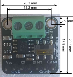
Adafruit CAN Pal (https://www.adafruit.com/product/5708 and https://cdn-learn.adafruit.com/downloads/pdf/adafruit-can-pal.pdf).