Qiskit: Difference between revisions
| Line 73: | Line 73: | ||
Quantum operations are reversible, thus the reversible computing. That makes some ''complications'' to the gate design. | Quantum operations are reversible, thus the reversible computing. That makes some ''complications'' to the gate design. | ||
=== Three Qubits === | === Three Qubits === | ||
Revision as of 10:32, 26 November 2020
Introduction
https://quantum-computing.ibm.com/
https://quantum-computing.ibm.com/challenges/fall-2020
https://quantum-computing.ibm.com/jupyter/user/IBMQuantumChallenge2020/week-1/ex_1a_en.ipynb
Installation
Installation https://qiskit.org/documentation/install.html
conda create -n qiskit python=3
conda activate qiskit
pip install qiskit /////_OR_////// pip install qiskit[visualization]
Did not work using Python 3.9. Instead, downgrade to Python 3.8.3 in your virtual environment.
conda create -n qiskit python=3
conda activate qiskit
conda install python=3.8.3
pip install qiskit ///////_OR_////// pip install qiskit[visualization]
Set up the Spyder IDE https://stackoverflow.com/questions/30170468/how-to-run-spyder-in-virtual-environment#47615445
Setting Up Qiskit
https://qiskit.org/textbook/ch-states/representing-qubit-states.html
from qiskit import QuantumCircuit, execute, Aer

qc = QuantumCircuit(1)  # Create a quantum circuit with one qubit
initial_state = [0,1]   # Define initial_state as |1>
qc.initialize(initial_state, 0) # Apply initialisation operation to the 0th qubit
qc.draw('text')  # Let's view our circuit (text drawing is required for the 'Initialize' gate due to a known bug in qiskit)

backend = Aer.get_backend('statevector_simulator') # Tell Qiskit how to simulate our circuit
result = execute(qc,backend).result() # Do the simulation, returning the result
out_state = result.get_statevector()
print(out_state) # Display the output state vector
from qiskit.visualization import plot_histogram, plot_bloch_vector
qc.measure_all()
qc.draw()
result = execute(qc,backend).result()
counts = result.get_counts()
plot_histogram(counts)Take superposition as initial state
initial_state = [1/sqrt(2), 1j/sqrt(2)] # Define state |q>The Bloch Sphere
from qiskit_textbook.widgets import plot_bloch_vector_spherical
coords = [pi/2,0,1] # [Theta, Phi, Radius]
plot_bloch_vector_spherical(coords) # Bloch Vector with spherical coordinates
Qiskit allows measuring in the Z-basis, only.
Theory
Quantum operations are reversible, thus the reversible computing. That makes some complications to the gate design.
Three Qubits

For universal computations we need more qubits. Eg. the AND gate is not reversible, and thus we need eg. Toffoli (CCNOT) gate.
Toffoli gate performs Failed to parse (SVG (MathML can be enabled via browser plugin): Invalid response ("Math extension cannot connect to Restbase.") from server "https://wikimedia.org/api/rest_v1/":): {\displaystyle X} on target qubit if both control cubits are set to state .
qc = QuantumCircuit(3)
a = 0
b = 1
t = 2
# Toffoli with control qubits a and b and target t
qc.ccx(a,b,t)
qc.draw()
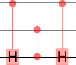
Toffoli using CNOTs uses fewer gates.
qc = QuantumCircuit(3)
qc.ch(a,t)
qc.cz(b,t)
qc.ch(a,t)
qc.draw()
AND gate is Toffoli gate with . . .

Failed to parse (SVG (MathML can be enabled via browser plugin): Invalid response ("Math extension cannot connect to Restbase.") from server "https://wikimedia.org/api/rest_v1/":): {\displaystyle \text{CCNOT}(x,y,z) = (x,y,( x \and y ) \otimes z )} gives the reversible NAND Failed to parse (SVG (MathML can be enabled via browser plugin): Invalid response ("Math extension cannot connect to Restbase.") from server "https://wikimedia.org/api/rest_v1/":): {\displaystyle \text{NAND}(x,y) = \text{CCNOT}(x,y,1) = (x,y,( x \and y ) \otimes 1 )}
NAND gate is
Clifford Gates
Exercises
Week 1
Week 2
Week 3
