Generate pwm using ic 555: Difference between revisions
From wikiluntti
| Line 15: | Line 15: | ||
<math> | <math> | ||
\begin{align} | \begin{align} | ||
T_\text{on} = 0.693 (R_1 + R_2) C \\ | T_\text{on} &= 0.693 (R_1 + R_2) C \\ | ||
T_\text{off} = 0.693 R_2 C \\ | T_\text{off} &= 0.693 R_2 C \\ | ||
f &= \frac{1.44}{(R_1 + 2R_2)C} | |||
\end{align} | \end{align} | ||
</math> | </math> | ||
Revision as of 12:28, 3 August 2024
Introduction
IC 555 is an astable multivibrator (oscillator).
Frequency: The ON time is defined by the time taken to its capacitor to charge to 1/e level through pin7 resistor, and the OFF time is the discharging time of the capacitor through pin7.
Theory
Method 1
![]()

Method 2: with diodes
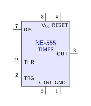
555 internal design and theory
See https://www.electronicshub.org/555-timer-pwm/
and the internal circuit looks like below:
References
https://www.homemade-circuits.com/how-to-use-ic-555-for-generating-pwm/