ESP32 Easy short tutorial: Difference between revisions
| Line 166: | Line 166: | ||
== Bluetooth == | == Bluetooth == | ||
== HC-12 Radio link == | |||
The simple code to test radiolink. | |||
Connect | |||
* VCC => 3.3V | |||
* GNDN => GND | |||
* RXD => TX2 (17) | |||
* TXD=> RX2 (16) | |||
* SET => 5 | |||
<syntaxhighlight lang="C"> | |||
#define RXD2 16 //(RX2) | |||
#define TXD2 17 //(TX2) | |||
#define HC12 Serial2 //Hardware serial 2 on the ESP32 | |||
void setup() | |||
{ | |||
pinMode(5, OUTPUT); | |||
digitalWrite(5, LOW); //Normally HIGH, LOW for settings | |||
Serial.begin(115200); // Serial port to computer | |||
HC12.begin(9600, SERIAL_8N1, RXD2, TXD2); // Serial port to HC12 | |||
} | |||
void loop() | |||
{ | |||
while (HC12.available()) { | |||
// If HC-12 has data | |||
Serial.write(HC12.read()); // Send the data to Serial monitor | |||
} | |||
while (Serial.available()) { | |||
// If we have data from Serial monitor | |||
HC12.write(Serial.read()); // Send that data to HC-12 | |||
} | |||
} | |||
</syntaxhighlight> | |||
== CANbus TJA1051 T/3 == | == CANbus TJA1051 T/3 == | ||
Revision as of 15:53, 17 December 2025
Introduction
1
My ESP32 is 32WROOM-32
- https://docs.cirkitdesigner.com/component/61475118-b098-4ce5-a041-f984abcb9607/esp32-wroom
- https://www.az-delivery.de/en/products/esp32-developmentboard
- (https://www.mouser.com/datasheet/2/891/esp-wroom-32_datasheet_en-1223836.pdf)
-

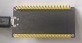
Front side
-
Back side and connections
-
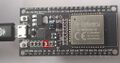
Tx light blinks when serial connection transfers data


Leds:
- Tx led blinks when transmitting data.
Pull Up Resistors
Enable pull up in Arduino-based ESP32 programming:
pinMode(13, INPUT_PULLUP); // Enable built-in pullup on pin 13
// Enable built-in pullup on GPIO12
  gpio_set_pull_mode(GPIO_NUM_18, GPIO_PULLUP_ENABLE);
Pull up resistors are between a digital input pin and the VCC. Two main purposes:
- Avoids issues with floating inputs.
- The default "ON" state for inputs like buttons and switches which actively pull the pin low. The pull up resistor keeps the circuit reading high until the button grounds the pin.
Some pins do not have pullup resistors:
- GPIO34
- GPIO35
- GPIO36
- GPIO39
Others do:
| Pin Name | GPIO Number | Pull Up? |
|---|---|---|
| GPIO0 | 0 | Yes |
| GPIO2 | 2 | Yes |
| GPIO4 | 4 | Yes |
| GPIO5 | 5 | Yes |
| GPIO12 | 12 | Yes |
| GPIO13 | 13 | Yes |
| GPIO14 | 14 | Yes |
| GPIO15 | 15 | Yes |
| GPIO25 | 25 | Yes |
| GPIO26 | 26 | Yes |
| GPIO27 | 27 | Yes |
| GPIO32 | 32 | Yes |
| GPIO33 | 33 | Yes |
For pins without built-in pull ups, or in output applications needing precise levels, you can add external pull up resistors. See the references for more information.
References:
Connect to Windows PC
See https://wiki.luntti.net/index.php?title=APC220_Radio;_Arduino#USB-TTL_converter
Uploading problems
Problem: Wrong boot mode detected (0x13)! The chip needs to be in download mode.
- press boot button on the esp32 board when run the code
- OR solder a 10uF capacitor between the EN pin and Ground (last pin on the ESP32 module). The EN pin on the ESP32 is used to enable or disable the chip; it must be pulled high to power on the device. If you want to enter programming mode, this pin should be low during boot, but it is generally recommended to keep it high for normal operation.
Problem: This chip is ESP32, not ESP32-S3. Wrong chip argument?
- Choose ESP32 Dev Module
Serial and Tx blink
Check that ESP32 works
void setup() {
    Serial.begin(9600);
}

void loop() {
  Serial.println("luntti.net");
  delay(500);
}
This should write a text to serial monitor every 0.5 secs and blink the Tx led at the same time.
Blink
Blink an internal led
No:(
Blink a led
-
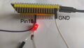
Blinking led. It is connected to pin18 and GND. Note that the (current limiting) resistor resistor is missing, because there is the pull-up resistor.

void setup() {
  pinMode(18, OUTPUT);
  // Enable built-in pullup on GPIO12
  gpio_set_pull_mode(GPIO_NUM_18, GPIO_PULLUP_ENABLE);
}

void loop() {
  digitalWrite(18, LOW);
  delay(1000);
  digitalWrite(18, HIGH);
  delay(1000);
}
Wifi
Bluetooth
HC-12 Radio link
The simple code to test radiolink.
Connect
- VCC => 3.3V
- GNDN => GND
- RXD => TX2 (17)
- TXD=> RX2 (16)
- SET => 5
#define RXD2 16	//(RX2)
#define TXD2 17	//(TX2)
#define HC12 Serial2  //Hardware serial 2 on the ESP32

void setup()
{
  pinMode(5, OUTPUT);
  digitalWrite(5, LOW);           //Normally HIGH, LOW for settings
  Serial.begin(115200);           // Serial port to computer
  HC12.begin(9600, SERIAL_8N1, RXD2, TXD2);      // Serial port to HC12
}

void loop()
{
  while (HC12.available()) {
    // If HC-12 has data
    Serial.write(HC12.read());      // Send the data to Serial monitor
  }
  while (Serial.available()) {
    // If we have data from Serial monitor
    HC12.write(Serial.read());      // Send that data to HC-12
  }
}
CANbus TJA1051 T/3
Adafruit T/3 should mean that it is 3.3V compatible. All TJA1051 variants are not.
Connections
Note that Rx pin need not to be connected while uploading programs into ESP32.
Pins
- Vcc: the same power as the logic level of your microcontroller (Arduino: 5V, ESP32 3.3V)
- GND - common ground for power and logic.
- RX - CAN receive/input. Connect to ESP32's RX. Do not connect when uploading.
- TX - CAN transmit/output. Despite sharing the 'RX' and 'TX' name with UART, they're not at all the same interface. Connect to ESP32's TX.
- CANh
- CANl
CarCluster
esp32_can library
ESP32-TWAI-CAN library
Install the library using Arduino IDEs library tools.
https://github.com/handmade0octopus/ESP32-TWAI-CAN
References
References
- Adafruit https://learn.adafruit.com/adafruit-can-pal
- Datasheet https://www.nxp.com/docs/en/data-sheet/TJA1051.pdf
Linux tutorial
Great linux tutorial: https://curiousstuff.eu/post/how-to-blink-the-damn-esp32-built-in-led/