Generate pwm using ic 555: Add a diode: Difference between revisions
From wikiluntti
(Created page with "== Method 2; Longer low time: Add a Diode == <gallery> Ic555 diode.pdf| The schematics. 555 diode Ranalysis.png| The simulations. </gallery> The added diode <math>D</math> shorts the out the resistor <math>R_2</math> during the charging cycle; thus the capacitor charges directly from <math>R_1</math> removing <math>R_2</math>, though a small leakage current will flow through it. The constants are modified due to the voltage drop of <math>D</math>. <math> \begin{align...") |
|||
| Line 14: | Line 14: | ||
f &= \frac{1.44}{(R_1 + 2R_2)C} | f &= \frac{1.44}{(R_1 + 2R_2)C} | ||
\end{align} | \end{align} | ||
</math> | |||
<math> | |||
pwm% = \frac{ T_\text{on} }{ T_\text{on} + T_\text{off}} = \frac{0.8 R_1 C}{0.8 R_1 C + 0.7 R_2 C } | |||
</math> | </math> | ||
The simulation file: [[File:555 diode 300 300.circuitjs.txt]] | The simulation file: [[File:555 diode 300 300.circuitjs.txt]] | ||
Revision as of 13:51, 5 August 2024
Method 2; Longer low time: Add a Diode
-
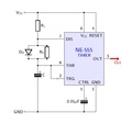
The schematics.
-
The simulations.
The added diode shorts the out the resistor during the charging cycle; thus the capacitor charges directly from removing , though a small leakage current will flow through it. The constants are modified due to the voltage drop of .
The simulation file: File:555 diode 300 300.circuitjs.txt


