Generate pwm using ic 555: Difference between revisions
| Line 119: | Line 119: | ||
Note that there exists multiple different placements for diodes! I do not follow all of these, yet. | Note that there exists multiple different placements for diodes! I do not follow all of these, yet. | ||
If needed a shorter high time and longer low time, a diode can be connected across <math>R_2</math> with cathode on the capacitor side. It is called the PWM mode. The charge and discharge timing of the capacitor <math>C</math> is bifurcated through separate channels using diodes. | If needed a shorter high time and longer low time, a diode can be connected across <math>R_2+0</math> with cathode on the capacitor side. It is called the PWM mode. The charge and discharge timing of the capacitor <math>C</math> is bifurcated through separate channels using diodes. Also, <math>R_2</math> is replaced with a potentiometer. | ||
See <ref>https://www.homemade-circuits.com/timer-ic-555-explained/</ref> for more text. This might be a good: <ref>https://www.electronics-tutorials.ws/waveforms/555-circuits-part-1.html</ref>. | See <ref>https://www.homemade-circuits.com/timer-ic-555-explained/</ref> for more text. This might be a good: <ref>https://www.electronics-tutorials.ws/waveforms/555-circuits-part-1.html</ref>. | ||
Revision as of 12:45, 5 August 2024
Introduction
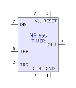
IC 555 is an astable multivibrator (oscillator).
Frequency: The ON time is defined by the time taken to its capacitor to charge to 2/3 (1/e??) level through pin7 resistor, and the OFF time is the discharging time of the capacitor through pin7, 1/3. See the precise numbers from [1].
Monostable state. Bistable state. [2]
Theory
Failed to parse (SVG (MathML can be enabled via browser plugin): Invalid response ("Math extension cannot connect to Restbase.") from server "https://wikimedia.org/api/rest_v1/":): {\displaystyle \begin{align} T_\text{on} &= 0.693 (R_1 + R_2) C \\ T_\text{off} &= 0.693 R_2 C \\ f &= \frac{1.44}{(R_1 + 2R_2)C} \end{align} }
The Failed to parse (SVG (MathML can be enabled via browser plugin): Invalid response ("Math extension cannot connect to Restbase.") from server "https://wikimedia.org/api/rest_v1/":): {\displaystyle R_1} resistance is much smaller than the resistance of the potentiometer, for example, 1K compared to 100K of the potentiometer. In that way we have 99% control over the charging and discharging resistance in the circuit. See https://electronics.stackexchange.com/questions/175967/how-do-i-use-pin5-to-control-duty-cycle-of-a-555-based-pwm
The output of the 555 timer can source a current of 200mA to the load.
- Use MOSFET (eg TIP122 Darlington transistor; 5A) for driving the motor.
To obtain a zero percent (0%) duty cycle, the oscillator need to stop oscillating. One option is to use a parallel resistor to use some of the current.
Method 1; the simple
-
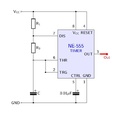
The simple 555 circuit.
-

The differences in C and output. Note that more than 50% pwm is not obtained
-
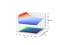
The surface and contour plot of the limits of the R1 and R2 values.


The capacitor is charging through Failed to parse (SVG (MathML can be enabled via browser plugin): Invalid response ("Math extension cannot connect to Restbase.") from server "https://wikimedia.org/api/rest_v1/":): {\displaystyle R_1}
and Failed to parse (SVG (MathML can be enabled via browser plugin): Invalid response ("Math extension cannot connect to Restbase.") from server "https://wikimedia.org/api/rest_v1/":): {\displaystyle R_2}
but discharges only through Failed to parse (SVG (MathML can be enabled via browser plugin): Invalid response ("Math extension cannot connect to Restbase.") from server "https://wikimedia.org/api/rest_v1/":): {\displaystyle R_2}
using IC 555. Thus Failed to parse (SVG (MathML can be enabled via browser plugin): Invalid response ("Math extension cannot connect to Restbase.") from server "https://wikimedia.org/api/rest_v1/":): {\displaystyle R_2}
should be a potentiometer.
The Failed to parse (SVG (MathML can be enabled via browser plugin): Invalid response ("Math extension cannot connect to Restbase.") from server "https://wikimedia.org/api/rest_v1/":): {\displaystyle 0.01 \mu} F capacitor is to ensure that the CTRL and GND stays on the same voltage level. The CTRL pin of the 555 is to level out any fluctuations in the power supply voltage that might affect the operation.
Failed to parse (SVG (MathML can be enabled via browser plugin): Invalid response ("Math extension cannot connect to Restbase.") from server "https://wikimedia.org/api/rest_v1/":): {\displaystyle \begin{align} T_\text{on} &= 0.693 (R_1 + R_2) C \\ T_\text{off} &= 0.693 R_2 C \\ f &= \frac{1.44}{(R_1 + 2R_2)C} \end{align} }
and
Failed to parse (SVG (MathML can be enabled via browser plugin): Invalid response ("Math extension cannot connect to Restbase.") from server "https://wikimedia.org/api/rest_v1/":): {\displaystyle \begin{align} \text{pwm}% & = \frac{T_\text{on}}{T_\text{on} + T_\text{off}} \\ &= \frac{ 0.693 (R_1 + R_2)C }{ 0.693 (R_1 + R_2) C + 0.693 R_2 C } \\ &= \frac{0.693C}{0.693 C} \frac{ R_1 + R_2}{R_1 + 2R_2} \\ &= \frac{ R_1 + R_2}{R_1 + 2R_2} \\ \end{align} }
The limits of Failed to parse (SVG (MathML can be enabled via browser plugin): Invalid response ("Math extension cannot connect to Restbase.") from server "https://wikimedia.org/api/rest_v1/":): {\displaystyle \text{pwm}%}
Failed to parse (SVG (MathML can be enabled via browser plugin): Invalid response ("Math extension cannot connect to Restbase.") from server "https://wikimedia.org/api/rest_v1/":): {\displaystyle \begin{align} \lim_{R_2 \to 0} \text{pwm}% &= \lim_{R_2 \to 0} \frac{ R_1 + R_2}{R_1 + 2R_2} \to \frac{ R_1 + 0}{R_1 + 0} = 1 \\ \lim_{R_2 \to \infty} \text{pwm}% &= \lim_{R_2 \to \infty} \frac{ R_1 + R_2}{R_1 + 2R_2} = \lim_{R_2 \to \infty} \frac{ R_2( \frac{R_1}{R_2} + 1)}{R_2( \frac{R_1}{R_2} + 2)} \to \frac{ 1}{2} \\ \end{align} }
But note that if Failed to parse (SVG (MathML can be enabled via browser plugin): Invalid response ("Math extension cannot connect to Restbase.") from server "https://wikimedia.org/api/rest_v1/":): {\displaystyle R_1} cannot be zero because then the discharge pin 7 would be shorted to Vcc.
See the attached python file which generates the surface and contour plot shown above: File:555limits.zip. It is a zipped python file.
File:555 simple 300 300.circuitjs.txt is the Falstad file to simulate the circuit. The image above is generated using Falstad circuit simulator.
| Failed to parse (SVG (MathML can be enabled via browser plugin): Invalid response ("Math extension cannot connect to Restbase.") from server "https://wikimedia.org/api/rest_v1/":): {\displaystyle R_1} | Failed to parse (SVG (MathML can be enabled via browser plugin): Invalid response ("Math extension cannot connect to Restbase.") from server "https://wikimedia.org/api/rest_v1/":): {\displaystyle R_2} | Failed to parse (SVG (MathML can be enabled via browser plugin): Invalid response ("Math extension cannot connect to Restbase.") from server "https://wikimedia.org/api/rest_v1/":): {\displaystyle C} | Failed to parse (SVG (MathML can be enabled via browser plugin): Invalid response ("Math extension cannot connect to Restbase.") from server "https://wikimedia.org/api/rest_v1/":): {\displaystyle T_\text{on}} | Failed to parse (SVG (MathML can be enabled via browser plugin): Invalid response ("Math extension cannot connect to Restbase.") from server "https://wikimedia.org/api/rest_v1/":): {\displaystyle T_\text{off}} | pwm% | Failed to parse (SVG (MathML can be enabled via browser plugin): Invalid response ("Math extension cannot connect to Restbase.") from server "https://wikimedia.org/api/rest_v1/":): {\displaystyle f} |
|---|---|---|---|---|---|---|
| 300 | 300 | 300 nF | 0.000125 | 0.0000624 | 0.67 | 5333 |
| 300 | 300 | 30 nF | 0.0000125 | 0.00000624 | 0.67 | 53333 |
| 300 | 300 | 3 uF | 0.00125 | 0.000624 | 0.67 | 533 |
| 3000 | 300 | 300 nF | 0.000686 | 0.0000624 | 0.92 | 1333 |
| 300 | 3000 | 300 nF | 0.000686 | 0.000624 | 0.52 | 762 |
| 300 | 30000 | 300 nF | 0.00630 | 0.00624 | 0.50 | 80 |
See the file File:555 simple calculations.ods for interactive Libre Office file.
As the resistance of Failed to parse (SVG (MathML can be enabled via browser plugin): Invalid response ("Math extension cannot connect to Restbase.") from server "https://wikimedia.org/api/rest_v1/":): {\displaystyle R_1} becomes much larger than Failed to parse (SVG (MathML can be enabled via browser plugin): Invalid response ("Math extension cannot connect to Restbase.") from server "https://wikimedia.org/api/rest_v1/":): {\displaystyle R_2} , the duty cycle increases towards unity (100%) as Failed to parse (SVG (MathML can be enabled via browser plugin): Invalid response ("Math extension cannot connect to Restbase.") from server "https://wikimedia.org/api/rest_v1/":): {\displaystyle R_2} approaches zero. If the resistance of Failed to parse (SVG (MathML can be enabled via browser plugin): Invalid response ("Math extension cannot connect to Restbase.") from server "https://wikimedia.org/api/rest_v1/":): {\displaystyle R_2} increases with respect to Failed to parse (SVG (MathML can be enabled via browser plugin): Invalid response ("Math extension cannot connect to Restbase.") from server "https://wikimedia.org/api/rest_v1/":): {\displaystyle R_1} , the duty cycle approaches 50% (or 1:1). It seems to be impossible to obtain less than 50% duty cycle with this system; Thus, only about half range can be achieved.
How to get the pwm% smaller than 50%. Add a diode to short Failed to parse (SVG (MathML can be enabled via browser plugin): Invalid response ("Math extension cannot connect to Restbase.") from server "https://wikimedia.org/api/rest_v1/":): {\displaystyle R_2} during the charge cycle.
Method 2; Longer low time: Add a Diode
File:555 diode 300 300.circuitjs.txt
Method 2; Longer low time: Diodes
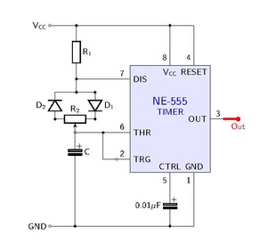
Note that there exists multiple different placements for diodes! I do not follow all of these, yet.
If needed a shorter high time and longer low time, a diode can be connected across Failed to parse (SVG (MathML can be enabled via browser plugin): Invalid response ("Math extension cannot connect to Restbase.") from server "https://wikimedia.org/api/rest_v1/":): {\displaystyle R_2+0} with cathode on the capacitor side. It is called the PWM mode. The charge and discharge timing of the capacitor Failed to parse (SVG (MathML can be enabled via browser plugin): Invalid response ("Math extension cannot connect to Restbase.") from server "https://wikimedia.org/api/rest_v1/":): {\displaystyle C} is bifurcated through separate channels using diodes. Also, Failed to parse (SVG (MathML can be enabled via browser plugin): Invalid response ("Math extension cannot connect to Restbase.") from server "https://wikimedia.org/api/rest_v1/":): {\displaystyle R_2} is replaced with a potentiometer.
See [4] for more text. This might be a good: [5].
Method 3: Transistor
The 555 can source or sink (supply or pass to ground) around 200mA, thus to drive larger currents we need an output circuit. The 555 will work from 5 to 15 volts, thus a same voltage source can be used. FOr controlling the motor we use TIP31 NPN transistor (max 3A).
Parts
- TIP31 NPN Transistor
- 12V Motor or a dimmable load
https://diyodemag.com/education/fundamentals_versatile_555_timer_pwm_control
- But more diodes
Method 3: MOSFET
Mosfet allows more current (they operate on a totally different electrical principle).
- BJT operation is based on current control. Less efficient (higher power dissipation). Lower input impedance. Superior linearity.
- Mosfet operation is based on voltage control. More efficient. Higher switching speed. Better thermal stability. High input impedance.
Method 2: More Diodes
The diodes are used for direction control and protection of the circuit.
555 internal design and theory
See https://www.electronicshub.org/555-timer-pwm/
and the internal circuit looks like below:
Simulation
Simulation is done using https://www.falstad.com/circuit/circuitjs.html simulation software. The corresponding editable circuit file is downloadable.
References
https://www.homemade-circuits.com/how-to-use-ic-555-for-generating-pwm/
https://www.electronicshub.org/555-timer-pwm/
- ↑ https://electronics.stackexchange.com/questions/454406/what-do-0-693-and-1-1-and-1-44-mean-in-ic-555-calculations/454443#454443
- ↑ https://www.build-electronic-circuits.com/555-timer/
- ↑ https://electronics.stackexchange.com/questions/175967/how-do-i-use-pin5-to-control-duty-cycle-of-a-555-based-pwm
- ↑ https://www.homemade-circuits.com/timer-ic-555-explained/
- ↑ https://www.electronics-tutorials.ws/waveforms/555-circuits-part-1.html
- ↑ https://diyodemag.com/education/fundamentals_versatile_555_timer_pwm_control
- ↑ https://how2electronics.com/pwm-based-dc-motor-speed-control-using-555-timer/