Generate pwm using ic 555: Difference between revisions
| Line 50: | Line 50: | ||
The 555 can source or sink (supply or pass to ground) around 200mA, thus to drive larger currents we need an output circuit. The 555 will work from 5 to 15 volts, thus a same voltage source can be used. FOr controlling the motor we use TIP31 NPN transistor (max 3A). | The 555 can source or sink (supply or pass to ground) around 200mA, thus to drive larger currents we need an output circuit. The 555 will work from 5 to 15 volts, thus a same voltage source can be used. FOr controlling the motor we use TIP31 NPN transistor (max 3A). | ||
Parts | |||
* TIP31 NPN Transistor | |||
* 12V Motor or a dimmable load | |||
== Method 3: MOSFET == | == Method 3: MOSFET == | ||
Revision as of 14:20, 3 August 2024
Introduction
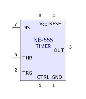
IC 555 is an astable multivibrator (oscillator).
Frequency: The ON time is defined by the time taken to its capacitor to charge to 2/3 (1/e??) level through pin7 resistor, and the OFF time is the discharging time of the capacitor through pin7, 1/3.
Monostable state. Bistable state. [1]
Theory

The Failed to parse (SVG (MathML can be enabled via browser plugin): Invalid response ("Math extension cannot connect to Restbase.") from server "https://wikimedia.org/api/rest_v1/":): {\displaystyle R_1} resistance is much smaller than the resistance of the potentiometer, for example, 1K compared to 100K of the potentiometer. In that way we have 99% control over the charging and discharging resistance in the circuit. See https://electronics.stackexchange.com/questions/175967/how-do-i-use-pin5-to-control-duty-cycle-of-a-555-based-pwm
The output of the 555 timer can source a current of 200mA to the load.
- Use MOSFET (eg TIP122 Darlington transistor; 5A) for driving the motor.
To obtain a zero percent (0%) duty cycle, the oscillator need to stop oscillating. One option is to use a parallel resistor to use some of the current.
Method 1; the simple
The capacitor is charging through Failed to parse (SVG (MathML can be enabled via browser plugin): Invalid response ("Math extension cannot connect to Restbase.") from server "https://wikimedia.org/api/rest_v1/":): {\displaystyle R_1} and Failed to parse (SVG (MathML can be enabled via browser plugin): Invalid response ("Math extension cannot connect to Restbase.") from server "https://wikimedia.org/api/rest_v1/":): {\displaystyle R_2} but discharges only through Failed to parse (SVG (MathML can be enabled via browser plugin): Invalid response ("Math extension cannot connect to Restbase.") from server "https://wikimedia.org/api/rest_v1/":): {\displaystyle R_2} using IC 555. Thus Failed to parse (SVG (MathML can be enabled via browser plugin): Invalid response ("Math extension cannot connect to Restbase.") from server "https://wikimedia.org/api/rest_v1/":): {\displaystyle R_2} should be a potentiometer.
The Failed to parse (SVG (MathML can be enabled via browser plugin): Invalid response ("Math extension cannot connect to Restbase.") from server "https://wikimedia.org/api/rest_v1/":): {\displaystyle 0.01 \mu} F capacitor is to ensure that the CTRL and GND stays on the same voltage level. The CTRL pin of the 555 is to level out any fluctuations in the power supply voltage that might affect the operation.
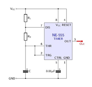
Failed to parse (SVG (MathML can be enabled via browser plugin): Invalid response ("Math extension cannot connect to Restbase.") from server "https://wikimedia.org/api/rest_v1/":): {\displaystyle \begin{align} T_\text{on} &= 0.693 (R_1 + R_2) C \\ T_\text{off} &= 0.693 R_2 C \\ f &= \frac{1.44}{(R_1 + 2R_2)C} \end{align} }
Method 2: Transistor
The 555 can source or sink (supply or pass to ground) around 200mA, thus to drive larger currents we need an output circuit. The 555 will work from 5 to 15 volts, thus a same voltage source can be used. FOr controlling the motor we use TIP31 NPN transistor (max 3A).
Parts
- TIP31 NPN Transistor
- 12V Motor or a dimmable load
Method 3: MOSFET
Method 2: More Diodes
The diodes are used for direction control and protection of the circuit.
555 internal design and theory
See https://www.electronicshub.org/555-timer-pwm/
and the internal circuit looks like below:
References
https://www.homemade-circuits.com/how-to-use-ic-555-for-generating-pwm/
https://www.electronicshub.org/555-timer-pwm/
- ↑ https://www.build-electronic-circuits.com/555-timer/
- ↑ https://electronics.stackexchange.com/questions/175967/how-do-i-use-pin5-to-control-duty-cycle-of-a-555-based-pwm
- ↑ https://diyodemag.com/education/fundamentals_versatile_555_timer_pwm_control
- ↑ https://how2electronics.com/pwm-based-dc-motor-speed-control-using-555-timer/