FEM and Blender: Difference between revisions
| (144 intermediate revisions by the same user not shown) | |||
| Line 1: | Line 1: | ||
== Introduction == | == Introduction == | ||
<gallery> | |||
225degrees blender.png| The door canopy with 22.5 degree supports. | |||
45degrees blender.png|The original idea with 45 deg supports. | |||
</gallery> | |||
* Blender | * Blender | ||
| Line 7: | Line 13: | ||
** quad remesher https://www.youtube.com/watch?v=kfQfU_cDRWE | ** quad remesher https://www.youtube.com/watch?v=kfQfU_cDRWE | ||
** Fix meshes https://github.com/evaherbst/Blender_remeshing_guide | ** Fix meshes https://github.com/evaherbst/Blender_remeshing_guide | ||
* FreeCAD | * FreeCAD | ||
* Gmsh https://gmsh.info/ | * Elmer https://www.elmerfem.org/blog/ Couldn't install on Arch Linux | ||
* Netgen https://ngsolve.org/ | * Gmsh https://gmsh.info/ Worked to create the mesh but not perfectly | ||
* OpenFOAM https://www.openfoam.com/ | * Netgen https://ngsolve.org/ as a part of FreeCAD. | ||
* Paraview https://www.paraview.org/ | * OpenFOAM https://www.openfoam.com/ Fluif FEM | ||
* Salome | * Paraview https://www.paraview.org/ Didn't try | ||
* TetGen | * Salome Didn't try | ||
* TetGen Didn't try | |||
Blender and CAD | Blender and CAD | ||
| Line 21: | Line 27: | ||
* Parts list | * Parts list | ||
** Using a script: Selected parts only, and don't apply rotations! https://github.com/kittengue-dot/Blender-Script-Export-Part-list https://www.youtube.com/watch?v=C1RZszKlojQ | ** Using a script: Selected parts only, and don't apply rotations! https://github.com/kittengue-dot/Blender-Script-Export-Part-list https://www.youtube.com/watch?v=C1RZszKlojQ | ||
** Copy and paste the script the Blender Python console. Copy the data to Spreadsheet and sort. | |||
<syntaxhighlight lang="python"> | <syntaxhighlight lang="python"> | ||
import bpy | import bpy | ||
print('Part, Section X (cm), Section Y (cm), Length Z (cm)') | |||
for obj in bpy.context.selected_objects: | |||
if obj.type == 'MESH': | |||
dimensions = obj.dimensions | |||
x = [0,0,0] | |||
x[0] = round(dimensions.x , 3) | |||
x[1] = round(dimensions.y , 3) | |||
x[2] = round(dimensions.z , 3) | |||
x.sort() | |||
print('Part: ', obj.name, ',', x[0], ', ', x[1], ', ', x[2] ) | |||
</syntaxhighlight> | |||
=== Measures === | |||
Many packages, eg | |||
< | * View -> Measure Tools | ||
* CAD<Measure | |||
== FreeCAD import == | == FreeCAD import == | ||
Steps: | Steps: | ||
* Export | * Export from Blender. If exporting STL, ''scale'' on export 1000x. Problems with [https://blender.stackexchange.com/questions/7910/what-is-non-manifold-geometry/7914 non-manifold geometry]. | ||
** Use Boolean | ** Use Boolean to make on mesh | ||
** Non-manifold: Select -> Select All by Trait -> Non Manifold, also the others from there. Remove the faces and then dissolve the edges (Limited Dissolve or X > Dissolve Edges). | |||
*** (Select Similar). This is often useful to select vertices with only one connecting edge | |||
*** (Select Linked) | |||
*** W > Specials > Remove doubles Doubles, | |||
** Check the normals outward: Edit mode, Select All, Mesh -> Normals -> Outward (Shift + N) | |||
** Eliminate the bolts and some holes | ** Eliminate the bolts and some holes | ||
* Part -> Create shape from mesh | * FreeCAD | ||
* Part -> MakeSolid | ** Part -> Create shape from mesh | ||
** Part -> MakeSolid | |||
| Line 72: | Line 77: | ||
** Use Part -> View -> Transparency to see the intersection points, if they persist. | ** Use Part -> View -> Transparency to see the intersection points, if they persist. | ||
** eg Netfabb cleans | ** eg Netfabb cleans | ||
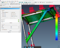
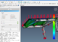
== FEM Calculations of the Door Canopy == | |||
Images of the displacement. | |||
<gallery> | |||
</gallery> | |||
=== Images === | |||
<gallery> | |||
VonMisesStress-98.png | |||
Maxshearstressmax-97.png | |||
MinPrincipalStressMaxMin.png | |||
MaxPrincipalStressMinMax.png | |||
DisplacementZminmax.png | |||
FEM 225x2.png | |||
FEM 225.png | |||
FEM 45short.png | |||
FEM perustajakatto45astetta tukipuu roof.png|Displacement Y | |||
FEM noSupports.png|Y | |||
DisplacementYmaxmin.png | |||
DisplacementXminmax.png | |||
DisplacementMag-97.png | |||
</gallery> | |||
=== Results === | |||
Material: Wood-Generic | |||
* Density 700 kg/m<sup>3</sup> | |||
* Young's Modulus 12.00 GPa | |||
* Poisson Ratio 0.05 | |||
Roof is done with fine mesh, no roofed with even finer mesh. | |||
{| class="wikitable sortable" | |||
|+ | |||
|- | |||
! rowspan=2 | Design | |||
! colspan=2 | Displacement magnitude | |||
! colspan=2 | Displacement X | |||
! colspan=2 | Displacement Y | |||
! colspan=2 | Displacement Z | |||
! colspan=2 | von Mises Stress | |||
! colspan=2 | Max Principal Stress | |||
! colspan=2 | Min Principal Stress | |||
! colspan=2 | Max Shear Stress | |||
|- | |||
! Min !! Max [mm] !! Min [µm] !! Max [µm] !! Min [µm] !! Max [µm] !! Min [mm] !! Max [nm] !! Min !! Max [kPa] !! Min [kPa] !! Max [kPa] !! Min [kPa] !! Max [kPa] !! Min !! Max [kPa] | |||
|- | |||
| No Rafters || 0.00 || 2.01 || -110 || 320 || 240 || 100 || -2.01 || 800.04 || 0.00 || 5847.87 || -191.14 || 6037.13 || -5486.84 || 285.32 || 0.00 || 2969.41 | |||
|- | |||
| 22.5° rafter || 0.00 || 0.22 || -17.67 || 92.32 || -46.55 || 14.54 || -0.23 || 164.74 || 0.00 || 2020.39 || -118.97 || 2101.76 || -1742,35 || 119.10 || 0.00 || 1014.03 | |||
|- | |||
| 22.5° × 2 rafters || 0.00 || 0.16 || -13.67 ||63.63 || -35.62 || 9.99 ||-0.15 || 148.73 || 0.00 || 1324.45 || -108.65 || 1142.64 || -1356.50 || 60.92 || 0 || 672.31 | |||
|- | |||
| 45° rafter short || 0.0 || 0.42 || -21.53 || 58.41 || -72.82 || 30.83 || -0.42 || 5650 || 0.0 || 2401.54 || -211.93 || 1492.78 || -2688.61 || 163.16 || 0.0 || 1238.34 | |||
|- | |||
| 45° rafter long || 0.0 || 0.29 || -150 || 27.54 || -27.47 || 44.55 || -0.28 || 18000 || 0.0 || 4428.06 || -452.01 || 3577.26 || -4490.38 || 177.60 || 0.0 || 2328.85 | |||
|- | |||
| No Rafters + Roof || 0.00 || 0.20 || -31.32 || 1.46 || -12.69 || 15.98 || -0.20 || 1810 || 0 | |||
|| 1250.0 || -184.54 || 1140.49 || -1295.94 || 126.83 || 0.0 || 628.53 | |||
|- | |||
| 22.5° rafter + Roof || 0.00 || 0.056 || -13.27 || 4.16 || -7.57 || 4.78 || -0.055 || 481.98 || 0.00 || 681.47 || -86.48 || 584.56 || -709.20 || 48.88 || 0.00 || 348.28 | |||
|- | |||
| 22.5° × 2 rafters + Roof || 0.00 || 0.051 || -12.77 || 3.01 ||-5.27 || 4.28 || -0.050 || 417.70 || 0.00 || 583.69 || -84.33 || 397.96 || -618.15 || 27.47 || 0.00 || 299.63 | |||
|- | |||
| 45° rafter short + Roof || 0.0 || 0.054 || -6.79 || 4.28 || -2.05 || 5.69 || -0.054 || 419.78 || 0.00 || 582.62 || -67.76 || 411.89 || -649.33 || 53.02 || 0.0 || 302.88 | |||
|- | |||
| 45° rafter long + Roof || 0.0 || 0.045 || -8.38 || 8.09 || -11.90 || 3.60 || -0.044 || 1010 || 0.0 || 828.26 || -95.27 || 619.46 || -865.24 || 62.89 || 0.0 || 421.55 | |||
|} | |||
=== Simulation parameters === | |||
* Roof Sheet: 1200 x 900 x 22 (distance 634 mm + 20 mm) and 1200 x 700 x 22 | |||
Material: Wood-Generic | |||
* Density 700 kg/m3 | |||
* Young's Modulus 12.00 GPa | |||
* Poisson Ratio 0.05 | |||
Force: 1000 N, downwards (about). | |||
{| class="wikitable sortable" | |||
|+ Caption text | |||
|- | |||
! Header text !! Nodes !! Triangles !! Tetrahedron !! Header text | |||
|- | |||
| No Rafters || 16413 || 5424 || 7786 || Example | |||
|- | |||
| 22.5° rafter || 20407 || 6684 || 9775 || Example | |||
|- | |||
| 22.5° × 2 rafters || 20185 || 6650 || 9627 || Example | |||
|- | |||
| 45° rafter || 101200 || 15184 || 63378 || Example | |||
|- | |||
| No Rafters + roof || 138706 || 29970 || 80746 || Example | |||
|- | |||
| 22.5° rafter + roof || 150122 || 31522 || 88019 || Example | |||
|- | |||
| 22.5° × 2 rafters + roof || 160384 || 33678 || 94172 || Example | |||
|- | |||
| 45° rafter short + roof || 143677 || 32766 || 82140 || Example | |||
|} | |||
Size | |||
{| class="wikitable" | |||
|- | |||
! Name !! Width !! Height !! Length | |||
|- | |||
| sivuvaaka || 40.0 || 60.0 || 1200.0 | |||
|- | |||
| sivuvaaka2 || 40.0 || 60.0 || 1200.0 | |||
|- | |||
| etulyhytpysty || 40.0 || 60.0 || 400.0 | |||
|- | |||
| lyhytvino2 || 40.0 || 60.0 || 1207.695 | |||
|- | |||
| pystyseina || 40.0 || 60.0 || 535.61 | |||
|- | |||
| pitkavino || 40.0 || 60.0 || 740.106 | |||
|- | |||
| lujyvino || 40.0 || 60.0 || 1207.695 | |||
|- | |||
| pystyseina2 || 40.0 || 60.0 || 535.61 | |||
|- | |||
| pitkavino2 || 40.0 || 60.0 || 740.106 | |||
|- | |||
| vinavase || 40.0 || 60.0 || 686.624 | |||
|- | |||
| takapalkki || 40.0 || 60.0 || 1270.0 | |||
|- | |||
| vinooikea2 || 40.0 || 60.0 || 771.684 | |||
|- | |||
| takapalkki.001 || 40.0 || 60.0 || 1270.0 | |||
|- | |||
| vinavase.002 || 40.0 || 60.0 || 686.624 | |||
|- | |||
| vinooikea1 || 40.0 || 60.0 || 771.684 | |||
|- | |||
| vinavase.004 || 40.0 || 60.0 || 686.624 | |||
|- | |||
| vinooikea || 40.0 || 60.0 || 771.684 | |||
|} | |||
=== Convergence tests === | |||
To ensure that the FEM simulation results converge, we try a simple simulation with different size of triangulation. | |||
== Workflow and test examples == | == Workflow and test examples == | ||
# Plan and sketch using Blender | |||
# Create the FEM model using FreeCAD | |||
# Do the simulations | |||
# Make the plans. | |||
Below is the non working idea. | |||
# Make the Blender mesh and export as .obj file | # Make the Blender mesh and export as .obj file | ||
# Make the mesh using GMSH or FreeCAD, and use FreeCAD to FEM calculations | # Make the mesh using GMSH or FreeCAD, and use FreeCAD to FEM calculations | ||
| Line 89: | Line 251: | ||
Cad mesh cube FreeCAD FEM.png|thumb|The FreeCAD FEM solver gives some results. | Cad mesh cube FreeCAD FEM.png|thumb|The FreeCAD FEM solver gives some results. | ||
Cad cube importToGMSH error.png|thumb|However, when importing to GMSH, it will produce an error. | Cad cube importToGMSH error.png|thumb|However, when importing to GMSH, it will produce an error. | ||
</gallery> | </gallery> | ||
| Line 96: | Line 256: | ||
<gallery> | <gallery> | ||
Cad cube stl imported NormalsDone gmsh ok.png|thumb|Meshing works, if the normals are done. | Cad cube stl imported NormalsDone gmsh ok.png|thumb|Meshing works, if the normals are done. | ||
Cad cube stl importToGMSH ok.png|thumb|If the cube is exported as STL, then GMSH will work better (if not normals done). | |||
Cad cube stl importToGMSH meshFails.png|thumb|The mesh generation does not work: "PLC Error: A segment and a facet intersect at point" and "Invalid boundary mesh (segment-facet intersection) on surface 1, intersection (0.333327,0.333327,1)". (if not normals done.) | |||
</gallery> | </gallery> | ||
| Line 104: | Line 267: | ||
Cad cubes Blender imported strange.png|thumb|When importing the Obj file back to Blender, the seems to be missing some faces. | Cad cubes Blender imported strange.png|thumb|When importing the Obj file back to Blender, the seems to be missing some faces. | ||
Cad cubes Blender imported NormalsDone.png|thumb|Seems that some of the normals are faced wrong way. In edit mode use (Ctrl+A) shift+N to fix this. | Cad cubes Blender imported NormalsDone.png|thumb|Seems that some of the normals are faced wrong way. In edit mode use (Ctrl+A) shift+N to fix this. | ||
Cad cube obj freeCAD normalsok FEM ok.png|thumb|Tetrahedron count is more than zero! It seems to work. | |||
Cad cube obj freeCAD normalsok FEM results ok.png|thumb|The FEM results seems to be working. The force is 10 N. | |||
</gallery> | |||
=== The Door Canopy === | |||
Couldn't do the model using Blender and Freecad/ Gmsh. | |||
Make it step by step. | |||
<gallery> | |||
Cad canopy 1st.png|thumb|First part works, though the dimensions are totally wrong. In the inset is the Blender Edit mode image of the same part. | |||
Cad canopy 1a.png|thumb|Set the scale from Blender export (1000x). Now the stress is visible, and dimensions are correct. Nice to work with familiar units. | |||
Cad canopy 2.png|thumb|Already second part (or third) gives problems. The mesh cannot be generated. This is with STL export. | |||
Cad canopy 2a OBJ.png|thumb|If tested using OBJ format, there will be some places without faces, and no tetrahedron in the mesh. | |||
</gallery> | </gallery> | ||
Gmsh | |||
<gallery> | |||
Cad canopy 1c gmsh.png|thumb|Gmsh makes the FEM mesh for the first part, and by refining the mesh, it will be clearer. | |||
Cad canopy 2b gmsh.png|thumb|Gmsh can use the second part, also. Need to check if FreeCAD can read that file. | |||
Cad canopy 2c FreeCADgmsh.png|thumb|FreeCAD has also Gmsh mesh generator. That will generate the mesh, but while solving gives an error: "Nodes, but no results found in frd file. It means there only is a mesh but no results in frd file. Usually this happens if CalculiX returned no results (happens on nonpositive jacobian determinant in at least one element)" | |||
Cad canopy 2d FreeCADgmsh.png|thumb|By trying again, it works! Force is 10 N. | |||
Cad canopy 2e FreeCADgmsh.png|thumb|Changed the Force to 100 N, and the maximum size of mesh to 10. The later increased the computation time a lot, the time being about 9 s. | |||
</gallery> | |||
== FreeCAD Tutorials == | |||
Good tutorials for noobies | |||
* https://www.youtube.com/watch?v=E14m5hf6Pvo | |||
* https://www.youtube.com/watch?v=5DoHT2lqVU4 | |||
== Theory == | == Theory == | ||
| Line 111: | Line 303: | ||
== References == | == References == | ||
The human character is Nathan https://sketchfab.com/3d-models/nathan-animated-003-walking-3d-man-143a2b1ea5eb4385ae90a73657aca3bc CC Attribution. | |||
Latest revision as of 00:05, 21 December 2025
Introduction
-
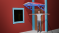
The door canopy with 22.5 degree supports.
-
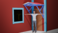
The original idea with 45 deg supports.


- Blender
- 3D print add-on (Check all)
- BFEX - Blender FEA Exporter https://github.com/MiguelDLM/BFEX
- Blendmsh https://github.com/senthurayyappan/blendmsh
- quad remesher https://www.youtube.com/watch?v=kfQfU_cDRWE
- Fix meshes https://github.com/evaherbst/Blender_remeshing_guide
- FreeCAD
- Elmer https://www.elmerfem.org/blog/ Couldn't install on Arch Linux
- Gmsh https://gmsh.info/ Worked to create the mesh but not perfectly
- Netgen https://ngsolve.org/ as a part of FreeCAD.
- OpenFOAM https://www.openfoam.com/ Fluif FEM
- Paraview https://www.paraview.org/ Didn't try
- Salome Didn't try
- TetGen Didn't try
Blender and CAD
- TinyCAD https://docs.blender.org/manual/en/4.1//addons/mesh/tinycad.html
- CadSketcher https://www.cadsketcher.com/
- Parts list
- Using a script: Selected parts only, and don't apply rotations! https://github.com/kittengue-dot/Blender-Script-Export-Part-list https://www.youtube.com/watch?v=C1RZszKlojQ
- Copy and paste the script the Blender Python console. Copy the data to Spreadsheet and sort.
import bpy

print('Part, Section X (cm), Section Y (cm), Length Z (cm)')
for obj in bpy.context.selected_objects:
    if obj.type == 'MESH':

        dimensions = obj.dimensions
        x = [0,0,0]
        x[0] = round(dimensions.x , 3)
        x[1] = round(dimensions.y , 3)
        x[2] = round(dimensions.z , 3)
        x.sort()
        print('Part: ', obj.name, ',', x[0], ', ', x[1], ', ', x[2] )
Measures
Many packages, eg
- View -> Measure Tools
- CAD<Measure
FreeCAD import
Steps:
- Export from Blender. If exporting STL, scale on export 1000x. Problems with non-manifold geometry.
- Use Boolean to make on mesh
- Non-manifold: Select -> Select All by Trait -> Non Manifold, also the others from there. Remove the faces and then dissolve the edges (Limited Dissolve or X > Dissolve Edges).
- (Select Similar). This is often useful to select vertices with only one connecting edge
- (Select Linked)
- W > Specials > Remove doubles Doubles,
- Check the normals outward: Edit mode, Select All, Mesh -> Normals -> Outward (Shift + N)
- Eliminate the bolts and some holes
- FreeCAD
- Part -> Create shape from mesh
- Part -> MakeSolid
Some problems (see a Part check Geometry)
- Geometry is a shell -- not a solid: a shell mesh on meshing
- Check this by right clicking on the mesh and printing mesh informations (Tasks: Node count vs Triangle count vs Tetrahedron count)
- Self intersections
- Use Boolean in Blender for all parts (both, if two are overlapping)
- Self intersecting meshes are considered dirty
- Use Part -> View -> Transparency to see the intersection points, if they persist.
- eg Netfabb cleans
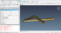
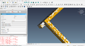
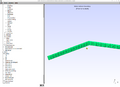
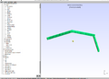
FEM Calculations of the Door Canopy
Images of the displacement.
Images
-

-
-

-
-
-
-
-
-
Displacement Y
-
Y
-
-
-
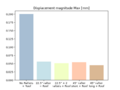


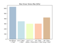
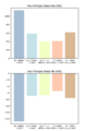
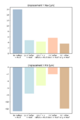
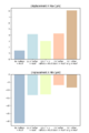
Results
Material: Wood-Generic
- Density 700 kg/m3
- Young's Modulus 12.00 GPa
- Poisson Ratio 0.05
Roof is done with fine mesh, no roofed with even finer mesh.
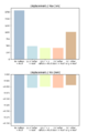
| Design | Displacement magnitude | Displacement X | Displacement Y | Displacement Z | von Mises Stress | Max Principal Stress | Min Principal Stress | Max Shear Stress | ||||||||
|---|---|---|---|---|---|---|---|---|---|---|---|---|---|---|---|---|
| Min | Max [mm] | Min [µm] | Max [µm] | Min [µm] | Max [µm] | Min [mm] | Max [nm] | Min | Max [kPa] | Min [kPa] | Max [kPa] | Min [kPa] | Max [kPa] | Min | Max [kPa] | |
| No Rafters | 0.00 | 2.01 | -110 | 320 | 240 | 100 | -2.01 | 800.04 | 0.00 | 5847.87 | -191.14 | 6037.13 | -5486.84 | 285.32 | 0.00 | 2969.41 |
| 22.5° rafter | 0.00 | 0.22 | -17.67 | 92.32 | -46.55 | 14.54 | -0.23 | 164.74 | 0.00 | 2020.39 | -118.97 | 2101.76 | -1742,35 | 119.10 | 0.00 | 1014.03 |
| 22.5° × 2 rafters | 0.00 | 0.16 | -13.67 | 63.63 | -35.62 | 9.99 | -0.15 | 148.73 | 0.00 | 1324.45 | -108.65 | 1142.64 | -1356.50 | 60.92 | 0 | 672.31 |
| 45° rafter short | 0.0 | 0.42 | -21.53 | 58.41 | -72.82 | 30.83 | -0.42 | 5650 | 0.0 | 2401.54 | -211.93 | 1492.78 | -2688.61 | 163.16 | 0.0 | 1238.34 |
| 45° rafter long | 0.0 | 0.29 | -150 | 27.54 | -27.47 | 44.55 | -0.28 | 18000 | 0.0 | 4428.06 | -452.01 | 3577.26 | -4490.38 | 177.60 | 0.0 | 2328.85 |
| No Rafters + Roof | 0.00 | 0.20 | -31.32 | 1.46 | -12.69 | 15.98 | -0.20 | 1810 | 0 | 1250.0 | -184.54 | 1140.49 | -1295.94 | 126.83 | 0.0 | 628.53 |
| 22.5° rafter + Roof | 0.00 | 0.056 | -13.27 | 4.16 | -7.57 | 4.78 | -0.055 | 481.98 | 0.00 | 681.47 | -86.48 | 584.56 | -709.20 | 48.88 | 0.00 | 348.28 |
| 22.5° × 2 rafters + Roof | 0.00 | 0.051 | -12.77 | 3.01 | -5.27 | 4.28 | -0.050 | 417.70 | 0.00 | 583.69 | -84.33 | 397.96 | -618.15 | 27.47 | 0.00 | 299.63 |
| 45° rafter short + Roof | 0.0 | 0.054 | -6.79 | 4.28 | -2.05 | 5.69 | -0.054 | 419.78 | 0.00 | 582.62 | -67.76 | 411.89 | -649.33 | 53.02 | 0.0 | 302.88 |
| 45° rafter long + Roof | 0.0 | 0.045 | -8.38 | 8.09 | -11.90 | 3.60 | -0.044 | 1010 | 0.0 | 828.26 | -95.27 | 619.46 | -865.24 | 62.89 | 0.0 | 421.55 |
Simulation parameters
- Roof Sheet: 1200 x 900 x 22 (distance 634 mm + 20 mm) and 1200 x 700 x 22
Material: Wood-Generic
- Density 700 kg/m3
- Young's Modulus 12.00 GPa
- Poisson Ratio 0.05
Force: 1000 N, downwards (about).
| Header text | Nodes | Triangles | Tetrahedron | Header text |
|---|---|---|---|---|
| No Rafters | 16413 | 5424 | 7786 | Example |
| 22.5° rafter | 20407 | 6684 | 9775 | Example |
| 22.5° × 2 rafters | 20185 | 6650 | 9627 | Example |
| 45° rafter | 101200 | 15184 | 63378 | Example |
| No Rafters + roof | 138706 | 29970 | 80746 | Example |
| 22.5° rafter + roof | 150122 | 31522 | 88019 | Example |
| 22.5° × 2 rafters + roof | 160384 | 33678 | 94172 | Example |
| 45° rafter short + roof | 143677 | 32766 | 82140 | Example |
Size
| Name | Width | Height | Length |
|---|---|---|---|
| sivuvaaka | 40.0 | 60.0 | 1200.0 |
| sivuvaaka2 | 40.0 | 60.0 | 1200.0 |
| etulyhytpysty | 40.0 | 60.0 | 400.0 |
| lyhytvino2 | 40.0 | 60.0 | 1207.695 |
| pystyseina | 40.0 | 60.0 | 535.61 |
| pitkavino | 40.0 | 60.0 | 740.106 |
| lujyvino | 40.0 | 60.0 | 1207.695 |
| pystyseina2 | 40.0 | 60.0 | 535.61 |
| pitkavino2 | 40.0 | 60.0 | 740.106 |
| vinavase | 40.0 | 60.0 | 686.624 |
| takapalkki | 40.0 | 60.0 | 1270.0 |
| vinooikea2 | 40.0 | 60.0 | 771.684 |
| takapalkki.001 | 40.0 | 60.0 | 1270.0 |
| vinavase.002 | 40.0 | 60.0 | 686.624 |
| vinooikea1 | 40.0 | 60.0 | 771.684 |
| vinavase.004 | 40.0 | 60.0 | 686.624 |
| vinooikea | 40.0 | 60.0 | 771.684 |
Convergence tests
To ensure that the FEM simulation results converge, we try a simple simulation with different size of triangulation.
Workflow and test examples
- Plan and sketch using Blender
- Create the FEM model using FreeCAD
- Do the simulations
- Make the plans.
Below is the non working idea.
- Make the Blender mesh and export as .obj file
- Make the mesh using GMSH or FreeCAD, and use FreeCAD to FEM calculations
Simple Cube
Works OK with the FreeCAD, not with the Gmsh
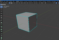
OBJ
-
The imported cube has double nodes, and the color is strange.
-
(If normals are fixed (shift+N in edit mode) the box will look better. This is not used in the following parts).
-
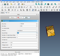
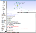
It works flawless in the FreeCAD.
-
The FreeCAD FEM solver gives some results.
-
However, when importing to GMSH, it will produce an error.


STL
-
Meshing works, if the normals are done.
-
If the cube is exported as STL, then GMSH will work better (if not normals done).
-
The mesh generation does not work: "PLC Error: A segment and a facet intersect at point" and "Invalid boundary mesh (segment-facet intersection) on surface 1, intersection (0.333327,0.333327,1)". (if not normals done.)


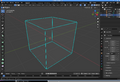
Two Cubes
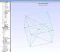
-
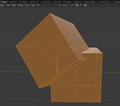
The two cubes made in Blender. The mesh looks fine, and there are none self intersecting nodes.
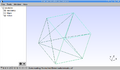
-
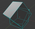
When importing the Obj file back to Blender, the seems to be missing some faces.
-
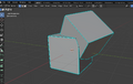
Seems that some of the normals are faced wrong way. In edit mode use (Ctrl+A) shift+N to fix this.
-
Tetrahedron count is more than zero! It seems to work.
-
The FEM results seems to be working. The force is 10 N.


The Door Canopy
Couldn't do the model using Blender and Freecad/ Gmsh.
Make it step by step.
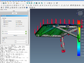
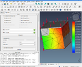
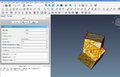
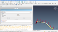
-
First part works, though the dimensions are totally wrong. In the inset is the Blender Edit mode image of the same part.
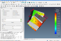
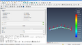
-
Set the scale from Blender export (1000x). Now the stress is visible, and dimensions are correct. Nice to work with familiar units.
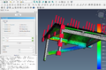
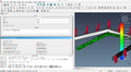
-
Already second part (or third) gives problems. The mesh cannot be generated. This is with STL export.
-
If tested using OBJ format, there will be some places without faces, and no tetrahedron in the mesh.


Gmsh
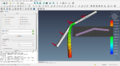
-
Gmsh makes the FEM mesh for the first part, and by refining the mesh, it will be clearer.
-
Gmsh can use the second part, also. Need to check if FreeCAD can read that file.
-
FreeCAD has also Gmsh mesh generator. That will generate the mesh, but while solving gives an error: "Nodes, but no results found in frd file. It means there only is a mesh but no results in frd file. Usually this happens if CalculiX returned no results (happens on nonpositive jacobian determinant in at least one element)"
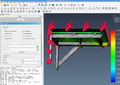
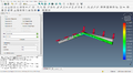
-
By trying again, it works! Force is 10 N.
-
Changed the Force to 100 N, and the maximum size of mesh to 10. The later increased the computation time a lot, the time being about 9 s.


FreeCAD Tutorials
Good tutorials for noobies
Theory
Frame formulas: https://structx.com/frames.html
References
The human character is Nathan https://sketchfab.com/3d-models/nathan-animated-003-walking-3d-man-143a2b1ea5eb4385ae90a73657aca3bc CC Attribution.