Arduino Sound Sensor: Difference between revisions
| (46 intermediate revisions by the same user not shown) | |||
| Line 1: | Line 1: | ||
== Introduction == | == Introduction == | ||
Measuring sound is difficult due to its logarithmic nature. There are digital and analog measuring systems available. Digital are either pure on/off or they might give I2C data. | |||
A good explenation about sensors is at https://www.atomic14.com/2020/09/12/esp32-audio-input | |||
== Digital Sound sensor == | |||
Simple sound sensor; output True or False. | Simple sound sensor; output True or False. | ||
== Code 1. The simple == | === Code 1. The simple === | ||
Tutorial page: https://arduinogetstarted.com/tutorials/arduino-sound-sensor | Tutorial page: https://arduinogetstarted.com/tutorials/arduino-sound-sensor | ||
| Line 27: | Line 33: | ||
} | } | ||
</syntaxhighlight> | </syntaxhighlight> | ||
=== Exercises === | |||
=== Code 1 === | |||
Turn on the one more LED if the sound is strong enough. | |||
<syntaxhighlight lang="C"> | |||
#include <FastLED.h> | |||
#define SENSOR_PIN 7 | |||
#define NUM_LEDS 10 | |||
#define LED_PIN 5 | |||
int soundState = HIGH; // the previous state from the input pin | |||
int numLeds = 0; | |||
CRGB leds[NUM_LEDS]; | |||
void setup() { | |||
Serial.begin(9600); | |||
pinMode(SENSOR_PIN, INPUT); | |||
FastLED.addLeds<WS2812B, LED_PIN, GRB>(leds, NUM_LEDS); | |||
FastLED.setBrightness(20); | |||
} | |||
void loop() { | |||
soundState = digitalRead(SENSOR_PIN); | |||
if (soundState){ | |||
numLeds++; | |||
} | |||
for (int i=0; i<min( numLeds, NUM_LEDS); i++){ | |||
leds[i] = CRGB::Green; | |||
FastLED.show(); | |||
} | |||
if (soundState){ | |||
Serial.println(""); | |||
Serial.println( soundState ); | |||
}else{ | |||
Serial.print("Schii"); | |||
} | |||
} | |||
</syntaxhighlight> | |||
== Code 2 == | |||
# Turn all the LEDS to black in the SetUp() | |||
# Add delay when sound is noticed (not two LEDs turning on at the same time). | |||
# turn of the last led after a while. | |||
=== Code 3: test === | |||
<syntaxhighlight lang="C"> | |||
#include <FastLED.h> | |||
// Arduino's pin connected to OUT pin of the sound sensor | |||
#define SENSOR_PIN 7 | |||
#define NUM_LEDS 10 | |||
#define LED_PIN 5 | |||
int soundState = HIGH; // the previous state from the input pin | |||
int numLeds = 0; | |||
CRGB leds[NUM_LEDS]; | |||
unsigned long turnOffStart; | |||
void setup() { | |||
Serial.begin(9600); | |||
pinMode(SENSOR_PIN, INPUT); | |||
FastLED.addLeds<WS2812B, LED_PIN, GRB>(leds, NUM_LEDS); | |||
FastLED.setBrightness(20); | |||
for (int i=0; i<NUM_LEDS; i++){ | |||
leds[i] = CRGB::Black; | |||
FastLED.show(); | |||
} | |||
turnOffStart = millis(); | |||
} | |||
void loop() { | |||
soundState = digitalRead(SENSOR_PIN); | |||
if (soundState){ | |||
numLeds++; | |||
turnOffStart = millis(); | |||
delay(50); | |||
} | |||
if (millis() - turnOffStart > 200){ | |||
turnOffStart = millis(); | |||
numLeds = max( 0, numLeds--); | |||
} | |||
for (int i = min( numLeds, NUM_LEDS); i<NUM_LEDS; i++){ | |||
leds[i] = CRGB::Black; | |||
FastLED.show(); | |||
} | |||
for (int i=0; i<min( numLeds, NUM_LEDS); i++){ | |||
leds[i] = CRGB::Green; | |||
FastLED.show(); | |||
} | |||
} | |||
</syntaxhighlight> | |||
== HQ: Gravity: Analog Sound Level Meter== | |||
https://www.dfrobot.com/product-1663.html and the Wiki https://wiki.dfrobot.com/Gravity__Analog_Sound_Level_Meter_SKU_SEN0232 | |||
== MAX4466 / GY4466 == | |||
MAX4466 Microphone Amplifier Module. Analog. | |||
== MAX9812 == | |||
== MAX9814 == | |||
=== Introduction === | |||
<gallery> | |||
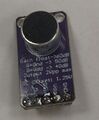
Arduino max9814 front.jpg|Front view of the MAX9814 sensor. | |||
Arduino max9814 back.jpg| The backside. | |||
Soundsensor micvalue.png|thumb|The values at somehow quiet room. The values are centered around 250. | |||
</gallery> | |||
Electret Microphone Amplifier - MAX9814 with Auto Gain Controller (AGC, built-in Automatic Gain Control) is a mic with integrated pre-amp plus audio amplifier. It is an analogic sensor. | |||
{| class="wikitable" | |||
|+ Caption text | |||
|- | |||
! Pin!! Arduino !! | |||
|- | |||
| Vdd || 5 V || Power supply (2.7 V - 5.5 V) | |||
|- | |||
| GND|| GND || GND | |||
|- | |||
| OUT || A0 || Analog audio output | |||
|- | |||
| AR ||No || Attack /release control for AGC timing | |||
|- | |||
| Gain || ||Selects fixed gain. Default 40 dB. | |||
|- | |||
| VDD (mic) || || mic? | |||
|} | |||
<syntaxhighlight lang="C"> | |||
const int micPin = A0; // Analog pin for MAX9814 output | |||
void setup() { | |||
Serial.begin(9600); | |||
} | |||
void loop() { | |||
int micValue = analogRead(micPin); | |||
Serial.println(micValue); | |||
delay(50); | |||
} | |||
</syntaxhighlight> | |||
=== Sound level meter === | |||
=== Frequency Detection === | |||
<gallery> | |||
400hz sinewave.png|400 Hz sine wave works perfectly. | |||
800hz sinewave.png|800 Hz sine wave works even better. | |||
Arduino findTheFreq.png|The code from the Arduino forum, post 42! | |||
</gallery> | |||
https://www.instructables.com/Arduino-Frequency-Detection/ | |||
* Direct port manipulation because it is faster than writing. | |||
* Interrupt routine at 38.5 kHZ: https://www.instructables.com/Arduino-Timer-Interrupts/ | |||
https://forum.arduino.cc/t/arduino-pitch-detection-in-realtime-using-autocorrelation-and-peak-detection/519783/42 | |||
* Post #42 of that thread. | |||
* 9615.4 samples per second. | |||
* Works! | |||
=== Guitar tuner === | |||
The guitar's strings should have the following frequencies: | |||
*E: 82.4 Hz | |||
*A: 110 Hz | |||
*D: 146.8 Hz | |||
*G: 196 Hz | |||
*B: 246.9 Hz | |||
*E: 329.6 Hz | |||
== INMP441 == | |||
Digital I2S MEMS microphone. | |||
== SPH0645 == | |||
Digital I2S MEMS microphone. | |||
== Hiwonder sound module == | |||
A microphone and LM358 amplifier. | |||
== LM358 Operational Amplifier Module == | |||
To amplify the analog data. | |||
Latest revision as of 17:53, 3 December 2025
Introduction
Measuring sound is difficult due to its logarithmic nature. There are digital and analog measuring systems available. Digital are either pure on/off or they might give I2C data.
A good explenation about sensors is at https://www.atomic14.com/2020/09/12/esp32-audio-input
Digital Sound sensor
Simple sound sensor; output True or False.
Code 1. The simple
Tutorial page: https://arduinogetstarted.com/tutorials/arduino-sound-sensor
#define SENSOR_PIN 7

int lastState = HIGH;  // the previous state from the input pin
int currentState;      // the current reading from the input pin

void setup() {
  Serial.begin(9600);
  pinMode(SENSOR_PIN, INPUT);
}

void loop() {
  currentState = digitalRead(SENSOR_PIN);
  if (currentState){
     Serial.println( currentState );
  }else{
     Serial.print("Schii");
  }

}
Exercises
Code 1
Turn on the one more LED if the sound is strong enough.
#include <FastLED.h>

#define SENSOR_PIN 7
#define NUM_LEDS 10
#define LED_PIN 5

int soundState = HIGH;  // the previous state from the input pin
int numLeds = 0;
CRGB leds[NUM_LEDS];


void setup() {
  Serial.begin(9600);
  pinMode(SENSOR_PIN, INPUT);
  FastLED.addLeds<WS2812B, LED_PIN, GRB>(leds, NUM_LEDS);
  FastLED.setBrightness(20);
}

void loop() {
  soundState = digitalRead(SENSOR_PIN);
  if (soundState){
    numLeds++;
  }

  for (int i=0; i<min( numLeds, NUM_LEDS); i++){
    leds[i] = CRGB::Green;
    FastLED.show();
  }

  if (soundState){
    Serial.println("");
     Serial.println( soundState );
  }else{
     Serial.print("Schii");
  }

}
Code 2
- Turn all the LEDS to black in the SetUp()
- Add delay when sound is noticed (not two LEDs turning on at the same time).
- turn of the last led after a while.
Code 3: test
#include <FastLED.h>

// Arduino's pin connected to OUT pin of the sound sensor
#define SENSOR_PIN 7
#define NUM_LEDS 10
#define LED_PIN 5

int soundState = HIGH;  // the previous state from the input pin
int numLeds = 0;
CRGB leds[NUM_LEDS];
unsigned long turnOffStart;

void setup() {
  Serial.begin(9600);
  pinMode(SENSOR_PIN, INPUT);
  FastLED.addLeds<WS2812B, LED_PIN, GRB>(leds, NUM_LEDS);
  FastLED.setBrightness(20);
  for (int i=0; i<NUM_LEDS; i++){
    leds[i] = CRGB::Black;
    FastLED.show();
  }
  turnOffStart = millis();

}


void loop() {
  soundState = digitalRead(SENSOR_PIN);
  if (soundState){
    numLeds++;
    turnOffStart = millis();
    delay(50);

  }
  if (millis() - turnOffStart > 200){
    turnOffStart = millis();
    numLeds = max( 0, numLeds--);
  }

  for (int i = min( numLeds, NUM_LEDS); i<NUM_LEDS; i++){
    leds[i] = CRGB::Black;
    FastLED.show();
  }

  for (int i=0; i<min( numLeds, NUM_LEDS); i++){
    leds[i] = CRGB::Green;
    FastLED.show();
  }

}
HQ: Gravity: Analog Sound Level Meter
https://www.dfrobot.com/product-1663.html and the Wiki https://wiki.dfrobot.com/Gravity__Analog_Sound_Level_Meter_SKU_SEN0232
MAX4466 / GY4466
MAX4466 Microphone Amplifier Module. Analog.
MAX9812
MAX9814
Introduction
-
Front view of the MAX9814 sensor.
-
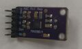
The backside.
-
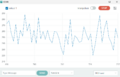
The values at somehow quiet room. The values are centered around 250.


Electret Microphone Amplifier - MAX9814 with Auto Gain Controller (AGC, built-in Automatic Gain Control) is a mic with integrated pre-amp plus audio amplifier. It is an analogic sensor.
| Pin | Arduino | |
|---|---|---|
| Vdd | 5 V | Power supply (2.7 V - 5.5 V) |
| GND | GND | GND |
| OUT | A0 | Analog audio output |
| AR | No | Attack /release control for AGC timing |
| Gain | Selects fixed gain. Default 40 dB. | |
| VDD (mic) | mic? |
const int micPin = A0;  // Analog pin for MAX9814 output

void setup() {
  Serial.begin(9600);
}

void loop() {
  int micValue = analogRead(micPin);
  Serial.println(micValue);
  delay(50);
}
Sound level meter
Frequency Detection
-
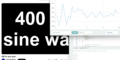
400 Hz sine wave works perfectly.
-
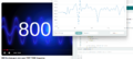
800 Hz sine wave works even better.
-
The code from the Arduino forum, post 42!


https://www.instructables.com/Arduino-Frequency-Detection/
- Direct port manipulation because it is faster than writing.
- Interrupt routine at 38.5 kHZ: https://www.instructables.com/Arduino-Timer-Interrupts/
- Post #42 of that thread.
- 9615.4 samples per second.
- Works!
Guitar tuner
The guitar's strings should have the following frequencies:
- E: 82.4 Hz
- A: 110 Hz
- D: 146.8 Hz
- G: 196 Hz
- B: 246.9 Hz
- E: 329.6 Hz
INMP441
Digital I2S MEMS microphone.
SPH0645
Digital I2S MEMS microphone.
Hiwonder sound module
A microphone and LM358 amplifier.
LM358 Operational Amplifier Module
To amplify the analog data.