Generate pwm using ic 555: Add a diode: Difference between revisions
| (7 intermediate revisions by the same user not shown) | |||
| Line 4: | Line 4: | ||
Ic555 diode.pdf| The schematics. | Ic555 diode.pdf| The schematics. | ||
555 diode Ranalysis.png| The simulations. | 555 diode Ranalysis.png| The simulations. | ||
555 diode RanalysisContour.png| The contour and surface plot of varying resistances. | |||
Ic555 diode2 R.pdf|Added the second diode. This will make the output identical if R<sub>1</sub> and R<sub>2</sub> are identical. | |||
Ic555 diode2 R3.pdf|One more resistance (or potentiometer) to make it more symmetric. This is discussed in more detailed in the next chapter, because the two potentiometers can be easily replaced by a one. | |||
</gallery> | </gallery> | ||
The added diode | The added diode ''D'' shorts the out the resistor ''R_2'' during the charging cycle; thus the capacitor charges directly from <math>R_1</math> removing ''R_2'', though a small '''leakage current''' will flow through it. The constants are modified due to the voltage drop of ''D''. | ||
<math> | <math> | ||
| Line 18: | Line 21: | ||
<math> | <math> | ||
pwm% = \frac{ T_\text{on} }{ T_\text{on} + T_\text{off}} | pwm% = \frac{ T_\text{on} }{ T_\text{on} + T_\text{off}} | ||
= \frac{0.8 R_1 }{0.8 R_1 + 0.7 R_2 } | = \frac{0.8 R_1 }{0.8 R_1 + 0.7 R_2 } | ||
</math> | </math> | ||
| Line 28: | Line 30: | ||
The simulation file: [[File:555 diode 300 300.circuitjs.txt]] | The simulation file: [[File:555 diode 300 300.circuitjs.txt]] | ||
The '''leakage current''' through ''R_2'' can be eliminated by introducing a second diode ''D_2'' in series with that. This will make the output identical if R<sub>1</sub> and R<sub>2</sub> are identical. See the image above. The corresponding simulation file is [[File:555 diodes2 300 300.circuitjs.txt]]. Adding one more resistance (or potentiometer) to make it more symmetric. This is discussed in more detailed in the next chapter, because the two potentiometers can be easily replaced by a one. The file is [[File:555 diodes2 300 300 300.circuitjs.txt]]. | |||
Latest revision as of 18:28, 5 August 2024
Method 2; Longer low time: Add a Diode
-
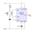
The schematics.
-
The simulations.
-
The contour and surface plot of varying resistances.
-
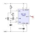
Added the second diode. This will make the output identical if R1 and R2 are identical.
-
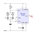
One more resistance (or potentiometer) to make it more symmetric. This is discussed in more detailed in the next chapter, because the two potentiometers can be easily replaced by a one.
The added diode D shorts the out the resistor R_2 during the charging cycle; thus the capacitor charges directly from removing R_2, though a small leakage current will flow through it. The constants are modified due to the voltage drop of D.
which simplifies to
The simulation file: File:555 diode 300 300.circuitjs.txt
The leakage current through R_2 can be eliminated by introducing a second diode D_2 in series with that. This will make the output identical if R1 and R2 are identical. See the image above. The corresponding simulation file is File:555 diodes2 300 300.circuitjs.txt. Adding one more resistance (or potentiometer) to make it more symmetric. This is discussed in more detailed in the next chapter, because the two potentiometers can be easily replaced by a one. The file is File:555 diodes2 300 300 300.circuitjs.txt.


