Switches and push buttons: Difference between revisions
| (19 intermediate revisions by the same user not shown) | |||
| Line 1: | Line 1: | ||
== Introduction == | == Introduction == | ||
[[File:Switch pull-up-resistor.png|thumb|Simple idea of switch and digital pins]] | |||
The idea is given in the image below. If the switch is open, the pin is connected through the resistor to 5V, but when switch is closed, the pin is grounded to 0V. The resistor is called ''pull-up resistor'', and prevents shorting to ground when the switch is closed. The other method is ''pull-down resistor''. | |||
Three methods to wire | See more different switches at https://learn.sparkfun.com/tutorials/button-and-switch-basics/all | ||
== Push Button == | |||
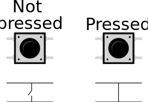
[[File:Arduino dpst button.svg|thumb|DPST button and function. The pins on the opposite side are connected, as is shown in the Figure.]] | |||
A double pole single throw push button micro switch (DPST) is a widely used button. Push button switches are often color coded to indicate their function. The opposite pins are connected, see https://docs.wokwi.com/parts/wokwi-pushbutton | |||
Three methods to wire because Arduino has built-in internal resistors: | |||
# External pullup or pulldown resistor: Use <code>pinMode( Button_pin, INPUT);</code> in the setup. | |||
# Internal resistor (20k-50k Ω): Use <code>INPUT_PULLUP</code> in setup <code>pinMode( Button_pin, INPUT_PULLUP);</code>. The default value is <code>HIGH</code> (1) and by pressing the button the state goes to <code>LOW</code>. | # Internal resistor (20k-50k Ω): Use <code>INPUT_PULLUP</code> in setup <code>pinMode( Button_pin, INPUT_PULLUP);</code>. The default value is <code>HIGH</code> (1) and by pressing the button the state goes to <code>LOW</code>. | ||
# The bad method: Use <code>pinMode( Button_pin, INPUT);</code> in the setup without any resistors. The default value will float between 0V and 5V: there is no internal or external voltage reference for the push button. | |||
# The bad method: | |||
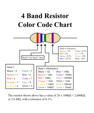
[[File:4-band-resistor-chart.svg|thumb|Resistor color codes.]] | |||
The external resistor should be somewhere between 4k and 20k Ohms. | |||
*1kΩ: Brown, Black, Red | |||
*2kΩ: Red, Black, Red | |||
*10kΩ: Brown, Black, Orange, (Gold). | |||
*20kΩ: Red, Black, Orange | |||
*50kΩ: Green, Black, Orange | |||
*100kΩ: Brown, Black, Yellow | |||
== Multiple buttons on One Analog Pin == | |||
[[File:Two switches analog.png|thumb]] | |||
Using different resistors on push buttons gives possibility to use many buttons with one analog input only. | |||
The proposed resistances are (https://www.instructables.com/How-to-Multiple-Buttons-on-1-Analog-Pin-Arduino-Tu/) | |||
* <math>R_1 = 1 </math>k | |||
* <math>R_2 = 2 </math>k | |||
* <math>R = 100 </math>k | |||
<syntaxhighlight lang="C"> | |||
void setup() { | |||
Serial.begin(9600); | |||
} | |||
void loop() { | |||
Serial.println( analogRead(A0) ); | |||
delay(100); | |||
} | |||
</syntaxhighlight> | |||
Latest revision as of 20:46, 26 July 2023
Introduction

The idea is given in the image below. If the switch is open, the pin is connected through the resistor to 5V, but when switch is closed, the pin is grounded to 0V. The resistor is called pull-up resistor, and prevents shorting to ground when the switch is closed. The other method is pull-down resistor.
See more different switches at https://learn.sparkfun.com/tutorials/button-and-switch-basics/all
Push Button

A double pole single throw push button micro switch (DPST) is a widely used button. Push button switches are often color coded to indicate their function. The opposite pins are connected, see https://docs.wokwi.com/parts/wokwi-pushbutton
Three methods to wire because Arduino has built-in internal resistors:
- External pullup or pulldown resistor: Use
pinMode( Button_pin, INPUT);in the setup. - Internal resistor (20k-50k Ω): Use
INPUT_PULLUPin setuppinMode( Button_pin, INPUT_PULLUP);. The default value isHIGH(1) and by pressing the button the state goes toLOW. - The bad method: Use
pinMode( Button_pin, INPUT);in the setup without any resistors. The default value will float between 0V and 5V: there is no internal or external voltage reference for the push button.

The external resistor should be somewhere between 4k and 20k Ohms.
- 1kΩ: Brown, Black, Red
- 2kΩ: Red, Black, Red
- 10kΩ: Brown, Black, Orange, (Gold).
- 20kΩ: Red, Black, Orange
- 50kΩ: Green, Black, Orange
- 100kΩ: Brown, Black, Yellow
Multiple buttons on One Analog Pin

Using different resistors on push buttons gives possibility to use many buttons with one analog input only.
The proposed resistances are (https://www.instructables.com/How-to-Multiple-Buttons-on-1-Analog-Pin-Arduino-Tu/)
- k
- k
- k
void setup() {
  Serial.begin(9600);
}

void loop() {
  Serial.println( analogRead(A0) );
  delay(100);
}


