Diesel Cycle: Difference between revisions
| (40 intermediate revisions by the same user not shown) | |||
| Line 1: | Line 1: | ||
== Introduction == | == Introduction == | ||
=== 1 === | |||
<gallery> | <gallery> | ||
| Line 6: | Line 8: | ||
</gallery> | </gallery> | ||
Ratio of specific heats (heat capacity ratio) is defined as | |||
<math> | <math> | ||
\gamma = \frac{ C_p }{ C_v } | \gamma = \frac{ C_p }{ C_v } | ||
</math> | </math> | ||
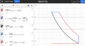
=== pV diagram === | |||
# Isentropic (adiabatic) expansion | # Isentropic (adiabatic) expansion | ||
| Line 19: | Line 23: | ||
'''Engine displacement''' is the cylinder volume swept by all of the pistons of a piston engine, excluding the combustion chambers. A '''combustion chamber''' is part of an internal combustion engine in which the fuel/air mix is burned. | '''Engine displacement''' is the cylinder volume swept by all of the pistons of a piston engine, excluding the combustion chambers. A '''combustion chamber''' is part of an internal combustion engine in which the fuel/air mix is burned. | ||
Only air is compressed, and then diesel fuel is injected directly into that hot, high-pressure air. | |||
* Cylinder pressure: ~30–80 bar | |||
* Injection pressure: ~1,000–2,500+ bar | |||
=== Diesel Cycle and Ideal Gas === | |||
There are three (3) different processes: | |||
# Isentropic <math>dU = nC_v dT = -pdV</math> | |||
# Isobaric <math>Q = \Delta U + p \Delta V</math> | |||
# Isochoric <math>\Delta Q = m c_v \Delta T</math> | |||
where the specific heat capacity at constant volume is <math>c_v = \frac{dQ/dT}{m}</math>. | |||
For a closed system, the total change in energy of a system is the sum of the work done and the heat added <math>dU = \delta W + \delta Q</math>, and the reversible work done on a system by changing the volume is <math>\delta W = - p dV</math>. Furthermore, for any transformation of an ideal gas, it is always true that <math>dU = nC_v dT</math>. | |||
If the system is reversible and adiabatic ('''isentropic''') <math>\delta Q = 0</math>, which gives | |||
<math> | |||
dU = \delta W + \delta Q = -pdV + 0 | |||
</math> | |||
<math> | |||
dU = nC_v dT = -pdV | |||
</math> | |||
For the constant pressure ('''isobaric process''') <math>\Delta p = 0</math> we have <math>W = \int p dV = p \Delta V</math>, and by applying the ideal gas law, we get <math>W = n R \Delta T</math>. | |||
For the '''Isochoric process''' <math>\Delta V=0</math>, and thus we have <math>dQ = dU = mc_v dT</math> which gives <math>\Delta Q = m c_v\Delta T</math>. | |||
<math> | |||
</math> | |||
=== Real gas: Air === | |||
Basic ideal gas model (good first approximation). Air is usually approximated as an ideal gas with: | |||
* Gas constant: | |||
** R≈287 J/(kg\cdotpK) | |||
** R≈287J/(kg\cdotpK) | |||
* Equation of state: | |||
* p=ρRT | |||
This works well at: | |||
* pressures near atmospheric | |||
* temperatures roughly 200–500 K | |||
“Generalized” ideal gas → temperature-dependent properties. To go beyond the simple model, you allow properties like heat capacity to vary with temperature: | |||
Heat capacity. For air, a common approximation is a polynomial | |||
<math> | |||
c_p(T)=a+bT. | |||
</math> | |||
Typical coefficients (for dry air, ~200–1000 K range): | |||
* a≈1005 | |||
* b≈0.1 | |||
More accurate forms come from NASA polynomials: | |||
<math> | |||
\frac{c_p}R=a_1+a_2T+a_3T^2+a_4T^3+a_5T^4 | |||
</math> | |||
Which are widely used in CFD and thermodynamics. | |||
Compressibility factor Z (real gas correction). If you want a generalized ideal gas, you often introduce <math>p=Z\rho RT</math>. Where | |||
* Z=1 → ideal gas | |||
* Z≠1 → real gas behavior | |||
For air: | |||
* At normal conditions: Z≈1 | |||
* At high pressure: use virial expansion | |||
<math> | |||
Z=1+\frac{B(T)}V+\frac{C(T)}{V^2}+ \cdots | |||
\approx 1+ \frac{B(T)}{RT}p. | |||
</math> | |||
Mixture-based formulation (more fundamental). Air is a mixture mainly of: | |||
* N₂ (~78%) | |||
* O₂ (~21%) | |||
* Ar (~1%) | |||
<math> | |||
\begin{align} | |||
R &=\sum_i y_i R_i \\ | |||
c_p & = \sum_i y_ i c_{p,i}(T) | |||
\end{align} | |||
</math> | |||
== Realistic Diesel Cycle == | == Realistic Diesel Cycle == | ||
| Line 25: | Line 118: | ||
Cylinder.png| The size of the combustion chamber of MB W211. | Cylinder.png| The size of the combustion chamber of MB W211. | ||
</gallery> | </gallery> | ||
=== Ratio of specific heats γ === | |||
<math> | |||
\gamma = \frac{ \sum y_1 c_{p,i} }{ \sum y_1 ( c_{p,i} -R_u ) } | |||
</math> | |||
{| class="wikitable" | |||
|+ Caption text | |||
|- | |||
! Condition !! γ (approx.) | |||
|- | |||
| Stoichiometric || ~1.30–1.33 | |||
|- | |||
| Moderate lean || ~1.33–1.37 | |||
|- | |||
| Very lean (diesel) || ~1.37–1.40 | |||
|} | |||
=== Injection pressures === | |||
* Older systems: 200–500 bar | |||
* Modern common-rail: 1,000–2,500 bar | |||
* Latest systems: up to ~3,000 bar | |||
* Air pressure in cylinder: ~30–80 bar, which is the pressure of the combustion chamber. | |||
* Temperature: ~700–1000 K | |||
=== Diesel-air Mixture === | |||
Only diesel is ejected into the cylinder. Clean air comes in during the intake stroke. | |||
The heat capacity ratio (known as the adiabatic index) for a diesel-air mixture is typically around 1.4. | |||
{| class="wikitable" | |||
|+ Air-fuel ratio | |||
|- | |||
| 14.5:1 || Near-stoichiometric; good combustion efficiency but higher emissions. | |||
|- | |||
| 16:1 || Balanced performance; good power output and efficiency. | |||
|- | |||
| 18:1 || Lean burn; improved fuel economy but potential for higher NOx emissions. | |||
|} | |||
Diesel is a complicated compound, but it’s commonly approximated as a hydrocarbon like C<sub>12</sub>H<sub>23</sub> (or C<sub>12</sub>H<sub>26</sub>). Air is about 21% O<sub>2</sub> and 79% N<sub>2</sub>. Without nitrogen, the stoichiometric ratio is about | |||
C<sub>12</sub>H<sub>23</sub>+17.75O<sub>2</sub>→12CO<sub>2</sub>+11.5H<sub>2</sub>O | |||
and by including nitrogen, we get | |||
C<sub>12</sub>H<sub>23</sub>+17.75( O<sub>2</sub> + 3.76 N<sub>2</sub> )→12CO<sub>2</sub>+11.5H<sub>2</sub>O + 66.74 N<sub>2</sub>. | |||
The molar masses | |||
* Fuel: 167 g/mol | |||
* Air: 137.28 g/mol | |||
And the total air needed is 17.72 x 137.28 = 2436 g, which gives air-to-fuel-ratio to | |||
<math> | |||
AFR = \frac{2436}{167} = 14.6:1 | |||
</math> | |||
=== MB data === | |||
Motor: OM648. | |||
Mercedes Benz W211 (2003) | Mercedes Benz W211 (2003) | ||
* Engine displacement: 3222 cm<sup>3</sup> | * Engine displacement: 3222 cm<sup>3</sup> = 0.003222 m<sup>3</sup> | ||
* Bore x Stroke: 88.0 x 88.4 mm<sup>3</sup> | * Bore x Stroke: 88.0 x 88.4 mm<sup>3</sup> | ||
* Compression Ratio: | * Compression Ratio: 18.0 | ||
Bore x stroke gives V = 6xπ(8.8/2)<sup>2</sup> x 8.84 cm<sup>3</sup> = 3225.95cm<sup>3</sup>, which is rather close. | Bore x stroke gives V = 6xπ(8.8/2)<sup>2</sup> x 8.84 cm<sup>3</sup> = 3225.95cm<sup>3</sup>, which is rather close. | ||
<math> | |||
p_1 V_1^\gamma = \text{constant}_1 | |||
</math> | |||
=== 1 === | |||
=== 1 === | |||
=== 1 === | |||
Latest revision as of 21:36, 30 March 2026
Introduction
1
-
Diesel Cycle
-
Diesel Cycle


Ratio of specific heats (heat capacity ratio) is defined as

pV diagram
- Isentropic (adiabatic) expansion
- Isochoric cooling (Qout): Heat rejection. Power stroke ends, heat rejection starts.
- Isobaric compression: Exhaust
- Isobaric expansion: Intake
- Isentropic (adiabatic) compression
- Isobaric heating (Qin): Combustion of fuel (heat is added in a constant pressure;)
Engine displacement is the cylinder volume swept by all of the pistons of a piston engine, excluding the combustion chambers. A combustion chamber is part of an internal combustion engine in which the fuel/air mix is burned.
Only air is compressed, and then diesel fuel is injected directly into that hot, high-pressure air.
- Cylinder pressure: ~30–80 bar
- Injection pressure: ~1,000–2,500+ bar
Diesel Cycle and Ideal Gas
There are three (3) different processes:
- Isentropic
- Isobaric
- Isochoric


where the specific heat capacity at constant volume is .

For a closed system, the total change in energy of a system is the sum of the work done and the heat added , and the reversible work done on a system by changing the volume is . Furthermore, for any transformation of an ideal gas, it is always true that .


If the system is reversible and adiabatic (isentropic) , which gives


For the constant pressure (isobaric process) we have , and by applying the ideal gas law, we get .


For the Isochoric process , and thus we have which gives .


Real gas: Air
Basic ideal gas model (good first approximation). Air is usually approximated as an ideal gas with:
- Gas constant:
- R≈287 J/(kg\cdotpK)
- R≈287J/(kg\cdotpK)
- Equation of state:
- p=ρRT
This works well at:
- pressures near atmospheric
- temperatures roughly 200–500 K
“Generalized” ideal gas → temperature-dependent properties. To go beyond the simple model, you allow properties like heat capacity to vary with temperature:
Heat capacity. For air, a common approximation is a polynomial Typical coefficients (for dry air, ~200–1000 K range):

- a≈1005
- b≈0.1
More accurate forms come from NASA polynomials: Which are widely used in CFD and thermodynamics.

Compressibility factor Z (real gas correction). If you want a generalized ideal gas, you often introduce . Where

- Z=1 → ideal gas
- Z≠1 → real gas behavior
For air:
- At normal conditions: Z≈1
- At high pressure: use virial expansion

Mixture-based formulation (more fundamental). Air is a mixture mainly of:
- N₂ (~78%)
- O₂ (~21%)
- Ar (~1%)
Failed to parse (SVG (MathML can be enabled via browser plugin): Invalid response ("Math extension cannot connect to Restbase.") from server "https://wikimedia.org/api/rest_v1/":): {\displaystyle \begin{align} R &=\sum_i y_i R_i \\ c_p & = \sum_i y_ i c_{p,i}(T) \end{align} }
Realistic Diesel Cycle
-

The size of the combustion chamber of MB W211.

Ratio of specific heats γ

| Condition | γ (approx.) |
|---|---|
| Stoichiometric | ~1.30–1.33 |
| Moderate lean | ~1.33–1.37 |
| Very lean (diesel) | ~1.37–1.40 |
Injection pressures
- Older systems: 200–500 bar
- Modern common-rail: 1,000–2,500 bar
- Latest systems: up to ~3,000 bar
- Air pressure in cylinder: ~30–80 bar, which is the pressure of the combustion chamber.
- Temperature: ~700–1000 K
Diesel-air Mixture
Only diesel is ejected into the cylinder. Clean air comes in during the intake stroke.
The heat capacity ratio (known as the adiabatic index) for a diesel-air mixture is typically around 1.4.
| 14.5:1 | Near-stoichiometric; good combustion efficiency but higher emissions. |
| 16:1 | Balanced performance; good power output and efficiency. |
| 18:1 | Lean burn; improved fuel economy but potential for higher NOx emissions. |
Diesel is a complicated compound, but it’s commonly approximated as a hydrocarbon like C12H23 (or C12H26). Air is about 21% O2 and 79% N2. Without nitrogen, the stoichiometric ratio is about
C12H23+17.75O2→12CO2+11.5H2O
and by including nitrogen, we get
C12H23+17.75( O2 + 3.76 N2 )→12CO2+11.5H2O + 66.74 N2.
The molar masses
- Fuel: 167 g/mol
- Air: 137.28 g/mol
And the total air needed is 17.72 x 137.28 = 2436 g, which gives air-to-fuel-ratio to

MB data
Motor: OM648.
Mercedes Benz W211 (2003)
- Engine displacement: 3222 cm3 = 0.003222 m3
- Bore x Stroke: 88.0 x 88.4 mm3
- Compression Ratio: 18.0
Bore x stroke gives V = 6xπ(8.8/2)2 x 8.84 cm3 = 3225.95cm3, which is rather close.
