Li Ion batteries: Difference between revisions
| (36 intermediate revisions by the same user not shown) | |||
| Line 81: | Line 81: | ||
== 21700 cells == | == 21700 cells == | ||
== Spot welding == | == Spot welding or soldering == | ||
Scratch the surface before soldering. Heat it up and apply the soldering tin. | |||
== 18650 & 3.3V or 3.0V output == | |||
=== Introduction === | |||
ESP32 should work at 3.0V or even at 2.2V. | |||
Use ESP32 with battery charger shield. | |||
TPS63031, TPS63001, TPS72633, TPS737xx, LD39080... | |||
https://solderingmind.com/3-7v-to-3-3v-regulator-circuit/ | |||
https://forum.arduino.cc/t/how-to-get-3-3v-from-3-7-lipo-battery/947573 | |||
=== LTC3440 === | |||
=== TPS63900 & LiPo === | |||
Lipo batteries, more current. | |||
=== === | |||
=== === | |||
=== === | |||
== 18650 & 5V output == | |||
To use with eg Arduino. | |||
Use buck booster (step up converter), eg | |||
* MOD-2344 | |||
=== TP-4056 charger === | |||
<gallery> | |||
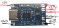
Tp4056.png|TP-4056 circuit with the corresponding labels. | |||
</gallery> | |||
TP-4056 (tp4056) chip is a lithium Ion battery charger for a single cell battery that protects the cell from over and under charging. There are two types of common breakout boards for this chip: | |||
* with only the charger chip on board. | |||
* with three chips on board (TP4056, FS2805A and DW01A), and indicator leds. Red charging, green (or blue) fully charged. | |||
The manufacturer's NanJing Top Power logo should be stamped on the logo. | |||
Output is 3.7 V. Thus not valid for ESP32 or Arduino. Input is either USB (5V) or 5V. | |||
https://easyelecmodule.com/tp4056-charging-module-the-ultimate-guide-for-beginners-pros/ | |||
https://electronics.stackexchange.com/questions/223366/tp4056-lithium-charger-module-issue | |||
https://jimlaurwilliams.org/wordpress/?p=4731 | |||
=== Okystar OKY3501-3 === | |||
DC/DC step-up 2..24V/5..28 2A | |||
=== TP-4056 charger and buck booster MT3068 === | |||
https://www.instructables.com/DC-DC-Boost-Converter-MT3608/ | |||
*Sometimes when you use the converter for the first time you will have to rotate the trimmer screw 5-10 full circles to get it working. Play with it until you get the feeling. | |||
* A 2 Amp fuse wired to battery + wire | |||
https://components101.com/modules/mt3608-2a-dc-dc-step-up-power-module | |||
https://www.daraz.lk/products/tp4056-mt3608-combo-18650-lithium-ion-battery-charger-and-boost-converter-for-arduino-esp32-node-mcu-diy-projects-i171530000.html | |||
=== Power bank and USB output === | |||
<gallery> | |||
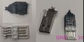
Usb pinout.jpg| USB provides +5V but be careful with the orientation. | |||
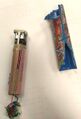
Powerbank 1.jpg| Powerbank is a great tool. | |||
</gallery> | |||
{| class="wikitable" style="text-align:center; background-color:#ffffff; color:#3E3D3D;" | |||
|- style="font-weight:bold; background-color:#4472C4;" | |||
! Pin No. | |||
! Wire Color | |||
! Signal | |||
! Description | |||
|- | |||
| style="font-weight:bold;" | 1 | |||
| Red | |||
| VCC | |||
| +5V | |||
|- style="background-color:#FFF;" | |||
| style="font-weight:bold;" | 2 | |||
| White | |||
| D- | |||
| Data- | |||
|- | |||
| style="font-weight:bold;" | 3 | |||
| Green | |||
| D+ | |||
| style="background-color:#D9E2F3;" | Data+ | |||
|- style="background-color:#FFF;" | |||
| style="font-weight:bold;" | 4 | |||
| Black | |||
| GND | |||
| Ground | |||
|} | |||
Latest revision as of 11:43, 21 March 2026
Introduction
1865 / 18650 cells
Diameter is 18 mm and length 65.0 mm.
Capacity
Measure it
- Battery Capacity Tester
- Constant Current Load (Multimeter and Resistor)
See the chart at https://www.batteryskills.com/18650-battery-capacity-chart/
Voltage
Note that the chemistry changes and thus these value might be a bit different. Be careful.
- Discharge cutoff voltage (the low voltage limit) is around 2.0V to 2.5V
- Over discharged < 2.5 V
- Discharged 3 V
- Nominal voltage is (usual) 3.6 V or 3.7 V.
- Full charge voltage is 4.2 V, which is the maximum voltage
Chemistry:
- Lithium Cobalt Oxide (LiCoO2): nominal voltage of 3.6V and is known for its high energy density.
- Lithium Manganese Oxide (LiMn2O4): a nominal voltage of 3.7V and offer thermal stability compared to LiCoO2
- Lithium Nickel Manganese Cobalt Oxide (NMC): a nominal voltage of 3.6V or 3.7V and provide a good balance of energy density and power capability.
- Lithium Iron Phosphate (LiFePO4): a nominal voltage of about 3.2V with excellent safety characteristics and long cycle life.
Over the upper limit (maximum voltage) battery will cause electrolyte breakdown and thermal runaway.
Below the lower Limit the battery’s chemistry may change irreversibly.
State of charge (SOC) and maximum voltage relation.
Charging
The standard charging voltage for most 18650 Li-ion batteries is 4.20 V ± 0.05 V. But slight charge and discharge will improve the battery reliablity and life cycles.
Slow charging is best (reduces stress and lengthens cell life.). Charge at less than 1 C current whenever possible, and at less than 0.5 C for resuscitating depleted cells.
Reviving over discharged batteries
Do not attempt these methods on:
- Physically damaged cells
- Cells that show signs of leakage
- Cells that heat up abnormally
- Cells with visible corrosion
Step 1. If voltage is under 2.5V, give a battery a brief pre-charge before full charging:
- Set power supply to 3.7V and 500mA current limit. OR Set your charger to 0.1C (e.g., 30mA for a 3000mAh cell).
- Connect discharged cell and charge for 2-5 minutes. OR charge until 2.5 V.
- Check voltage again. Stop when voltage reaches 3.0V.
- This small pre-charge brings the cell voltage up enough for normal charging.
Step 2. Charge depleted cells at 0.5 C or lower (slower is better). Then capacity test cycles to check cell health. Healthy 18650 cells should be:
- 2300+ mAh capacity
- <150-200 mΩ internal resistance
- <2%/month self-discharge
Also, Step 0: the jump start
- A fully charged 18650 battery to be connected to the dead battery
- Connect the positive terminals of both batteries for 1-2 seconds using a wire
- Check voltage with a multimeter
- Repeat 2-3 times until the dead battery reaches at least 2.5V
- Once above 2.5V, your regular charger should accept it
Step 0b: The Controlled Charging (batteries that still won’t take a charge after the jump start)
- Use a power supply or specialized battery charger that allows manual voltage control
- Set a current limit of 0.1C (for a 3000mAh battery 0.1C=300mA)
- Start at 2.0V and slowly increase in 0.5V increments
- Monitor temperature constantly – if the battery gets warm to the touch, stop immediately
- Once you reach 3.0V, switch to a standard charger
References
- https://nuranu.com/how-to-fix-dead-18650-battery/
- https://cnsbattery.com/what-are-the-ways-to-repair-an-18650-lithium-ion-battery-with-a-voltage-of-0v/
- https://secondlifestorage.com/index.php?threads/how-to-recover-18650-cells-safely-and-reliably.315/
- https://www.reddit.com/r/18650masterrace/comments/10dhiel/comment/j4n2dlh/?utm_source=share&utm_medium=web2x&context=3
21700 cells
Spot welding or soldering
Scratch the surface before soldering. Heat it up and apply the soldering tin.
18650 & 3.3V or 3.0V output
Introduction
ESP32 should work at 3.0V or even at 2.2V.
Use ESP32 with battery charger shield.
TPS63031, TPS63001, TPS72633, TPS737xx, LD39080...
https://solderingmind.com/3-7v-to-3-3v-regulator-circuit/
https://forum.arduino.cc/t/how-to-get-3-3v-from-3-7-lipo-battery/947573
LTC3440
TPS63900 & LiPo
Lipo batteries, more current.
18650 & 5V output
To use with eg Arduino.
Use buck booster (step up converter), eg
- MOD-2344
TP-4056 charger
-
TP-4056 circuit with the corresponding labels.

TP-4056 (tp4056) chip is a lithium Ion battery charger for a single cell battery that protects the cell from over and under charging. There are two types of common breakout boards for this chip:
- with only the charger chip on board.
- with three chips on board (TP4056, FS2805A and DW01A), and indicator leds. Red charging, green (or blue) fully charged.
The manufacturer's NanJing Top Power logo should be stamped on the logo.
Output is 3.7 V. Thus not valid for ESP32 or Arduino. Input is either USB (5V) or 5V.
https://easyelecmodule.com/tp4056-charging-module-the-ultimate-guide-for-beginners-pros/
https://electronics.stackexchange.com/questions/223366/tp4056-lithium-charger-module-issue
https://jimlaurwilliams.org/wordpress/?p=4731
Okystar OKY3501-3
DC/DC step-up 2..24V/5..28 2A
TP-4056 charger and buck booster MT3068
https://www.instructables.com/DC-DC-Boost-Converter-MT3608/
- Sometimes when you use the converter for the first time you will have to rotate the trimmer screw 5-10 full circles to get it working. Play with it until you get the feeling.
- A 2 Amp fuse wired to battery + wire
https://components101.com/modules/mt3608-2a-dc-dc-step-up-power-module
Power bank and USB output
-
USB provides +5V but be careful with the orientation.
-
Powerbank is a great tool.


| Pin No. | Wire Color | Signal | Description |
|---|---|---|---|
| 1 | Red | VCC | +5V |
| 2 | White | D- | Data- |
| 3 | Green | D+ | Data+ |
| 4 | Black | GND | Ground |