ESP32 Easy short tutorial: Difference between revisions
| (10 intermediate revisions by the same user not shown) | |||
| Line 414: | Line 414: | ||
</syntaxhighlight> | </syntaxhighlight> | ||
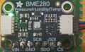
=== BME280 === | === BME280 Adafruit === | ||
This can be used either I2C or SPI. We will try I2C, and thus | <gallery> | ||
Bme280 greenlight.jpg| The Adafruit BME280 has SPI and I2C but also Stemma/QT connectors. Note the green on light when powered. | |||
</gallery> | |||
Adafruit BME280 works with either 5v or 3V logic. | |||
This can be used either I2C or SPI. We will try I2C, and thus for ESP32 | |||
* SCK is serial clock (CLK to 22), | * SCK is serial clock (CLK to 22), | ||
* SDI is data (SDA to 21) and | * SDI is data (SDA to 21) and | ||
* SDO determines the slave address (gnd or 1). | * SDO determines the slave address (gnd or 1). | ||
For my STEMMA QT cables, we follow the Qwiic convention (for Arduino): | |||
* Black for GND | |||
* Red for V+ | |||
* Blue for SDA | |||
* Yellow for SCL | |||
<syntaxhighlight lang="C"> | <syntaxhighlight lang="C"> | ||
| Line 519: | Line 530: | ||
} | } | ||
</syntaxhighlight> | </syntaxhighlight> | ||
== NTC Resistor == | |||
<gallery> | |||
Thermistor esp32.svg| The connectors. | |||
Thermistor esp32 data.png|Some data of the readings. When inserted into cold water, the analog value drops, and when taking it out, the values start rising again. | |||
</gallery> | |||
Thermometer, thermoresistor. NTC. See more physics on other Wikiluntti pages. | |||
Connect NTC to pin 34, use voltage divider as shown in the image. The resistor value should be the same as NTC (or PTC) resistor's value. | |||
<syntaxhighlight lang="C"> | |||
const int analogPin = 34; | |||
void setup() { | |||
Serial.begin(115200); | |||
} | |||
void loop() { | |||
int sensorValue = analogRead(analogPin); | |||
Serial.println( sensorValue ); | |||
delay(500); | |||
} | |||
</syntaxhighlight > | |||
== Linux tutorial == | == Linux tutorial == | ||
Great linux tutorial: https://curiousstuff.eu/post/how-to-blink-the-damn-esp32-built-in-led/ | Great linux tutorial: https://curiousstuff.eu/post/how-to-blink-the-damn-esp32-built-in-led/ | ||
Latest revision as of 12:33, 19 February 2026
Introduction
1
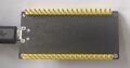
My ESP32 is 32WROOM-32
- https://docs.cirkitdesigner.com/component/61475118-b098-4ce5-a041-f984abcb9607/esp32-wroom
- https://www.az-delivery.de/en/products/esp32-developmentboard
- (https://www.mouser.com/datasheet/2/891/esp-wroom-32_datasheet_en-1223836.pdf)
-

Front side
-
Back side and connections
-
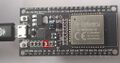
Tx light blinks when serial connection transfers data


Leds:
- Tx led blinks when transmitting data.
Pull Up Resistors
Enable pull up in Arduino-based ESP32 programming:
pinMode(13, INPUT_PULLUP); // Enable built-in pullup on pin 13
// Enable built-in pullup on GPIO12
  gpio_set_pull_mode(GPIO_NUM_18, GPIO_PULLUP_ENABLE);
Pull up resistors are between a digital input pin and the VCC. Two main purposes:
- Avoids issues with floating inputs.
- The default "ON" state for inputs like buttons and switches which actively pull the pin low. The pull up resistor keeps the circuit reading high until the button grounds the pin.
Some pins do not have pullup resistors:
- GPIO34
- GPIO35
- GPIO36
- GPIO39
Others do:
| Pin Name | GPIO Number | Pull Up? |
|---|---|---|
| GPIO0 | 0 | Yes |
| GPIO2 | 2 | Yes |
| GPIO4 | 4 | Yes |
| GPIO5 | 5 | Yes |
| GPIO12 | 12 | Yes |
| GPIO13 | 13 | Yes |
| GPIO14 | 14 | Yes |
| GPIO15 | 15 | Yes |
| GPIO25 | 25 | Yes |
| GPIO26 | 26 | Yes |
| GPIO27 | 27 | Yes |
| GPIO32 | 32 | Yes |
| GPIO33 | 33 | Yes |
For pins without built-in pull ups, or in output applications needing precise levels, you can add external pull up resistors. See the references for more information.
References:
Connect to Windows PC
See https://wiki.luntti.net/index.php?title=APC220_Radio;_Arduino#USB-TTL_converter
Uploading problems
Problem: Wrong boot mode detected (0x13)! The chip needs to be in download mode.
- press boot button on the esp32 board when run the code
- OR solder a 10uF capacitor between the EN pin and Ground (last pin on the ESP32 module). The EN pin on the ESP32 is used to enable or disable the chip; it must be pulled high to power on the device. If you want to enter programming mode, this pin should be low during boot, but it is generally recommended to keep it high for normal operation.
Problem: This chip is ESP32, not ESP32-S3. Wrong chip argument?
- Choose ESP32 Dev Module
Serial and Tx blink
Check that ESP32 works
void setup() {
    Serial.begin(9600);
}

void loop() {
  Serial.println("luntti.net");
  delay(500);
}
This should write a text to serial monitor every 0.5 secs and blink the Tx led at the same time.
Blink
Blink an internal led
No:(
Blink a led
-
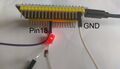
Blinking led. It is connected to pin18 and GND. Note that the (current limiting) resistor resistor is missing, because there is the pull-up resistor.

void setup() {
  pinMode(18, OUTPUT);
  // Enable built-in pullup on GPIO12
  gpio_set_pull_mode(GPIO_NUM_18, GPIO_PULLUP_ENABLE);
}

void loop() {
  digitalWrite(18, LOW);
  delay(1000);
  digitalWrite(18, HIGH);
  delay(1000);
}
Wifi
Bluetooth
HC-12 Radio link
Images


Theory
UART (Universal asynchronous receiver-transmitter) sends data bits one by one, from the least to most significant, framed by start and stop bits so that precise timing is handled by the communication channel. The ESP32 supports up to three UART interfaces (UART0, UART1, UART2).
- UART0 is usually reserved for communication with the serial monitor during upload and debugging. However, you can also use it for communication with other devices after uploading the code if the Serial Monitor is not needed.
- UART1 and UART2 are available to communicate with external devices.
The UART pins (Like I2C and SPI pin) can be mapped to any GPIO pin on the ESP32. However, they have a default pin assignment on most board models.
| UART port | TX | RX |
|---|---|---|
| UART0 | GPIO 1 | GPIO 3 |
| UART1 | GPIO 10 | GPIO 9 |
| UART2 | GPIO 17 | GPIO 16 |
Simple program
The simple code to test radiolink.
Connect
- VCC => 3.3V
- GNDN => GND
- RXD => TX2 (17)
- TXD=> RX2 (16)
- SET => 5
#define RXD2 16	//(RX2)
#define TXD2 17	//(TX2)
#define HC12 Serial2  //Hardware serial 2 on the ESP32

void setup()
{
  pinMode(5, OUTPUT);
  digitalWrite(5, LOW);           //Normally HIGH, LOW for settings
  Serial.begin(115200);           // Serial port to computer
  HC12.begin(9600, SERIAL_8N1, RXD2, TXD2);      // Serial port to HC12
}

void loop()
{
  while (HC12.available()) {
    // If HC-12 has data
    Serial.write(HC12.read());      // Send the data to Serial monitor
  }
  while (Serial.available()) {
    // If we have data from Serial monitor
    HC12.write(Serial.read());      // Send that data to HC-12
  }
}
Transmit data
A simple program to transmit data every second.
#define RXD2 16	//(RX2)
#define TXD2 17	//(TX2)
#define HC12 Serial2  //Hardware serial 2 on the ESP32

int x = 100;
unsigned long previousMillis = 0;
const long interval = 1000;

void setup(){
  Serial.begin(115200);
  HC12.begin(9600, SERIAL_8N1, RXD2, TXD2);
}

void loop() {
  unsigned long currentMillis = millis();
  if (currentMillis - previousMillis >= interval) {
      previousMillis = currentMillis;
      x = x + 1;
      HC12.println(x);
  }
}
CANbus TJA1051 T/3
Adafruit T/3 should mean that it is 3.3V compatible. All TJA1051 variants are not.
Connections
Note that Rx pin need not to be connected while uploading programs into ESP32.
Pins
- Vcc: the same power as the logic level of your microcontroller (Arduino: 5V, ESP32 3.3V)
- GND - common ground for power and logic.
- RX - CAN receive/input. Connect to ESP32's RX. Do not connect when uploading.
- TX - CAN transmit/output. Despite sharing the 'RX' and 'TX' name with UART, they're not at all the same interface. Connect to ESP32's TX.
- CANh
- CANl
CarCluster
esp32_can library
ESP32-TWAI-CAN library
Install the library using Arduino IDEs library tools.
https://github.com/handmade0octopus/ESP32-TWAI-CAN
References
References
- Adafruit https://learn.adafruit.com/adafruit-can-pal
- Datasheet https://www.nxp.com/docs/en/data-sheet/TJA1051.pdf
Motor Controller L293D
Wiring and code
Though it can be used to drive to motors, this will guide only one. Use the following wiring and the program.

//Motor_1 Connection
#define ENABLE_1    14
#define MOTOR_1_A   27
#define MOTOR_1_B   26

void setup() {
  Serial.begin(9600);
  Serial.println("Motor Init..");

  pinMode(MOTOR_1_A, OUTPUT);
  pinMode(MOTOR_1_B, OUTPUT);
  pinMode(ENABLE_1, OUTPUT);

  digitalWrite(MOTOR_1_A, LOW);
  digitalWrite(MOTOR_1_B, LOW);
  analogWrite(ENABLE_1, LOW);
}

void loop() {
 //Spin the motor forwards
 digitalWrite(MOTOR_1_A, HIGH);
 digitalWrite(MOTOR_1_B, LOW);
 analogWrite(ENABLE_1, 200);
 delay(2000);

 //Spin the motor backwards
 digitalWrite(MOTOR_1_A, LOW);
 digitalWrite(MOTOR_1_B, HIGH);
 analogWrite(ENABLE_1, 100);
 delay(2000);
}
The Enable pins control how fast the motors spin.
The chip has two direction control pins for each motor. The IN1 and IN2 pins control the spinning direction of motor A etc
| IN1 | IN2 | Spinning direction |
|---|---|---|
| 0 | 0 | OFF |
| 1 | 0 | Forward |
| 0 | 1 | Backward |
| 1 | 1 | OFF |
The L293D has four ground pins, and all of them are internally connected. They are used with heat dissipation by connecting these pins to a large copper pour or ground plane on the PCB.
References
https://lastminuteengineers.com/l293d-dc-motor-arduino-tutorial/
https://www.hackster.io/Arnov_Sharma_makes/esp32-x-l293d-motor-board-a9a7af
https://www.youtube.com/watch?v=aDBF9Yj04MU
Some sensors
MSA311
I2C bus, so connect
- SDA to GPIO 21 and
- SCL (serial clock line) to GPIO 22
Use commmands (set or get) below to change parameters.
#include <Wire.h>
#include <Adafruit_MSA301.h>
#include <Adafruit_Sensor.h>

Adafruit_MSA311 msa;

void setup(void) {
  Serial.begin(115200);
  msa.begin();
}

void loop() {
  sensors_event_t event;
  msa.getEvent(&event);

  /* Display the results (acceleration is measured in m/s^2) */
  Serial.print(""); Serial.print(event.acceleration.x);
  Serial.print(", "); Serial.print(event.acceleration.y);
  Serial.print(", "); Serial.print(event.acceleration.z);
  Serial.println();

  delay(100);
}
To change the properties use following commands in setup(void).
  //msa.setDataRate(MSA301_DATARATE_31_25_HZ);
  //msa.setPowerMode(MSA301_SUSPENDMODE); //Normal, Lowpower, Suspend
  //msa.setBandwidth(MSA301_BANDWIDTH_31_25_HZ);
  //msa.setRange(MSA301_RANGE_2_G);
  //msa.setResolution(MSA301_RESOLUTION_14 );
BME280 Adafruit
-
The Adafruit BME280 has SPI and I2C but also Stemma/QT connectors. Note the green on light when powered.

Adafruit BME280 works with either 5v or 3V logic. This can be used either I2C or SPI. We will try I2C, and thus for ESP32
- SCK is serial clock (CLK to 22),
- SDI is data (SDA to 21) and
- SDO determines the slave address (gnd or 1).
For my STEMMA QT cables, we follow the Qwiic convention (for Arduino):
- Black for GND
- Red for V+
- Blue for SDA
- Yellow for SCL
/*********
  Complete project details at https://randomnerdtutorials.com
*********/

#include <Wire.h>
#include <Adafruit_Sensor.h>
#include <Adafruit_BME280.h>

#define SEALEVELPRESSURE_HPA (1013.25)

Adafruit_BME280 bme; // I2C
unsigned long delayTime;

void setup() {
  Serial.begin(9600);
  Serial.println(F("BME280 test"));

  bool status;

  // default settings
  // (you can also pass in a Wire library object like &Wire2)
  status = bme.begin(0x76);
  if (!status) {
    Serial.println("Could not find a valid BME280 sensor, check wiring!");
    while (1);
  }
}


void loop() {
  printValues();
  delay(delayTime);
}

void printValues() {
  Serial.print(" ");  Serial.print(bme.readTemperature());
  Serial.print(", ");  Serial.print(bme.readPressure() / 100.0F);
  Serial.print(", ");  Serial.print(bme.readAltitude(SEALEVELPRESSURE_HPA));
  Serial.print(", "); Serial.print(bme.readHumidity());

  Serial.println();
}
SD Card Reader
The logic levels and voltage, see https://www.makerguides.com/sd-card-module-with-esp32/
My bigger reader needs +5V, does not work properly with 3.3V
- 3V3 ↔ 3.3V
- CS ↔ GPIO 5
- MOSI ↔ GPIO 23
- CLK ↔ GPIO 18
- MISO ↔ GPIO 19
- GND ↔ GND
#include <SD.h>
#define PIN_SPI_CS 5 // The ESP32 pin GPIO5

File myFile;


void save_data() {
    myFile = SD.open("/data.csv", FILE_APPEND);
    if(!myFile){
      Serial.println("Failed to open file for appending");
      return;
    }
    struct timeval tv_now;
    gettimeofday(&tv_now, NULL);
    int64_t time_us = (int64_t)tv_now.tv_sec * 1000000L + (int64_t)tv_now.tv_usec;

    myFile.print(time_us);
    myFile.print(",");
    myFile.println("a");
    myFile.close();
}

void setup() {
  Serial.begin(9600);
  if (!SD.begin(PIN_SPI_CS)) {
    while (1) {
      Serial.println(F("SD CARD FAILED, OR NOT PRESENT!"));
      delay(1000);
    }
  }

  Serial.println(F("SD CARD INITIALIZED."));
}

void loop() {
  save_data();
}
NTC Resistor
-

The connectors.
-

Some data of the readings. When inserted into cold water, the analog value drops, and when taking it out, the values start rising again.

Thermometer, thermoresistor. NTC. See more physics on other Wikiluntti pages.
Connect NTC to pin 34, use voltage divider as shown in the image. The resistor value should be the same as NTC (or PTC) resistor's value.
const int analogPin = 34;

void setup() {
  Serial.begin(115200);
}

void loop() {
  int sensorValue = analogRead(analogPin);
  Serial.println( sensorValue );

  delay(500);
}
Linux tutorial
Great linux tutorial: https://curiousstuff.eu/post/how-to-blink-the-damn-esp32-built-in-led/