FlySky FS-i6 and FS-iA10B: Difference between revisions
From wikiluntti
(→iBUS) |
|||
| (3 intermediate revisions by the same user not shown) | |||
| Line 1: | Line 1: | ||
== Introduction == | == Introduction == | ||
=== Technical details === | |||
Flysky FS-i6X 10CH 2.4GHz AFHDS RC Sender | |||
iBUS: iBUS protocol. | iBUS: iBUS protocol. | ||
| Line 5: | Line 9: | ||
=== iBUS === | === iBUS === | ||
Unfortunately not all FlySky receivers support the iBus. The following ones are recommended: FS-X6B, FS-IA6B and FS-A8S. (Not the one I have:() | Unfortunately not all FlySky receivers support the iBus. The following ones are recommended: FS-X6B, FS-IA6B and FS-A8S. (Not the one I have:() but the Medium article[<ref>https://medium.com/@werneckpaiva/how-to-read-rc-signal-with-arduino-using-flysky-ibus-73448bc924eb Medium article</ref>] includes FS-iA10B receiver, also. | ||
| Line 12: | Line 16: | ||
* The values received for each servo channel are between 1000 (hex eE8) and 2000 (hex 7D0) with neutral sub trim setting, which corresponds with the pulse width in microseconds for most servos. | * The values received for each servo channel are between 1000 (hex eE8) and 2000 (hex 7D0) with neutral sub trim setting, which corresponds with the pulse width in microseconds for most servos. | ||
See the example wiring on that Github page. | See the example wiring on that Github page or below: | ||
<gallery> | |||
Fs-ia10b.png|Example wiring. The rightmost pins are for iBUS signal and the leftmost for sensor iBUS. | |||
</gallery> | |||
== Transmitter FS-i6 == | == Transmitter FS-i6 == | ||
Latest revision as of 16:13, 21 November 2025
Introduction
Technical details
Flysky FS-i6X 10CH 2.4GHz AFHDS RC Sender
iBUS: iBUS protocol.
iBUS
Unfortunately not all FlySky receivers support the iBus. The following ones are recommended: FS-X6B, FS-IA6B and FS-A8S. (Not the one I have:() but the Medium article[[1]] includes FS-iA10B receiver, also.
https://github.com/bmellink/IBusBM:
- A half-duplex to control multiple servos and motors using a single digital line.
- The values received for each servo channel are between 1000 (hex eE8) and 2000 (hex 7D0) with neutral sub trim setting, which corresponds with the pulse width in microseconds for most servos.
See the example wiring on that Github page or below:
-
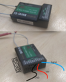
Example wiring. The rightmost pins are for iBUS signal and the leftmost for sensor iBUS.
