DIY Lawnmower 2023: Difference between revisions
| (24 intermediate revisions by the same user not shown) | |||
| Line 17: | Line 17: | ||
== Theory == | == Theory == | ||
=== Rotary Encoders or a Shaft Encoder === | |||
Two main types of rotary encoder: absolute (angle transducer) and incremental. | |||
* Mechanical (eg potentiometer) | |||
* Optical (sensitive to dust) | |||
* Capacitive | |||
* On-axis magnetic () | |||
* Off-axis magnetic | |||
Rotary pulse encoder; Eg 600 ppr (pulses per rotation). | |||
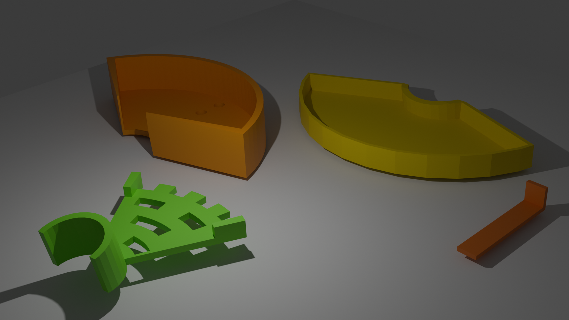
=== Gray code 3d STL files === | |||
<gallery> | |||
Lawnmower gray5.jpg |Caption1 | |||
Lawnmower gray4.jpg |Caption2 | |||
Lawnmower gray3.jpg |Caption2 | |||
Lawnmower gray2.jpg |Caption2 | |||
Lawnmower gray1.jpg |Caption2 | |||
</gallery> | |||
=== 3d design with Blender === | |||
[[File:Gray blend.png|The 50 deg Gray Code Disc]] | |||
60 degree limit; 16 segments. | |||
# Create a cylinder with 16x6 = 96 vertices; Radius 35; Depth 3. | |||
# Edit mode; extrude radially; scale s using the following numbers (which makes the difference of the radii the same). The data is found on [[File:Gracode_percentages.ods]]. The difference <math>d=\frac{R-r_1}{4}</math> | |||
{| class="wikitable" | |||
|+ Caption text | |||
|- | |||
! Radii !! Subtraction (d=0.825) !! Coeffiecient | |||
|- | |||
| R<sub>max</sub> || 7 || | |||
|- | |||
| R || 6.6 || 0.943 | |||
|- | |||
| r<sub>4</sub> || 5.775 || 0.875 | |||
|- | |||
| r<sub>3</sub> || 4.95 || 0.857 | |||
|- | |||
| r<sub>2</sub> || 4.125 || 0.8333 | |||
|- | |||
| r<sub>1</sub> || 3.3 || 0.8 | |||
|} | |||
# Make the cylindrical object which is to be attached to the axis. The angle is 100 deg. | |||
# Interesting but not working method: Cube; Hole; Simple Deform; Array | |||
The blend file: [[File:Gray disc.zip]] | |||
Sizes | |||
* Diameter of the axis: 25 mm | |||
* Width: 10 cm | |||
* Length: 7 cm (4.5 cm) | |||
* Height: Less than 26 mm | |||
* Diameter of the LDR is 0.51 mm | |||
Four + two (4+2) radii. | |||
* 7 / 6 = 1.1 cm | |||
=== Steering === | === Steering === | ||
| Line 386: | Line 447: | ||
Tip speed. The faster the blades move the sharper, more define the cut... impact energy | Tip speed. The faster the blades move the sharper, more define the cut... impact energy | ||
* 16,500 blade tip speed | * Anything over 90 m/s is fine. | ||
* WB mfg are up near 17k or 18k. Husqvarna WB with a tip speed of 15.9k. | * 84 m/s (16,500 fpm) blade tip speed | ||
* blade tip speed with | * WB mfg are up near 86 m/s or 91 m/s (17k or 18k fpm). Husqvarna WB with a tip speed of 81 m/s (15.9k). | ||
* blade tip speed with 94 m/s | |||
* the design of the deck. | * the design of the deck. | ||
Blades available from a shop | |||
* 32cm | |||
* 33cm | |||
* 38cm veitsiterä | |||
* 42cm | |||
* 43cm veitsiterä (bio) | |||
* 46cm veitsiterä (akkukäyttöinen) | |||
* 48cm veitsiterä (bio, akku) | |||
* 49cm | |||
* 50cm | |||
* 51cm | |||
* 53cm (myös 2x, eli 107 cm) 42" | |||
* 56cm (bioleikkaava) | |||
For example (at 97 m/s blade speed, 3.5 m/s ground speed, running single blades--so you get two "cuts" per revolution): | |||
* 30.5cm blade: 6048 rpm (!), 1.8 cm of ground travel between cuts (in/cut) | |||
* 42cm blade: 4398 rpm, 2.5 cm | |||
* 46cm blade: 4032 rpm, 2.7 cm | |||
* 53cm blade: 3455, 3 cm | |||
* 61cm blade: 3023, 3.5 cm | |||
The blade should spin at approximately 3000 RPM (revolutions per minute) to cut grass efficiently. ANSI standards: the tip of the blade should spin at a speed no greater than 97 m/s. | |||
'''Trimmer mower''' or '''field and brush mower''' for a very long grass | |||
Latest revision as of 21:43, 17 June 2025
Introduction
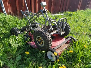
2 wheel drive using kids ATV chassis with 3" wheels without differential but with steering, 2x350W motor; speed controller. The grass cutter is a part from an old lawn mower. The ATV is steerable, thus a rotation measurement device is needed so that the motor will not burn.
https://www.kuldnebors.ee/search/search.mec?pob_action=search&search_O_string=atv&search_source=kwc
Arduino + GPS + IMU (Differential GPS).
Consider also
- ArduPilot https://ardupilot.org/rover/docs/gettit.html
- Cube Orange https://ardupilot.org/copter/docs/common-thecubeorange-overview.html
- OpenMower
Theory
Rotary Encoders or a Shaft Encoder
Two main types of rotary encoder: absolute (angle transducer) and incremental.
- Mechanical (eg potentiometer)
- Optical (sensitive to dust)
- Capacitive
- On-axis magnetic ()
- Off-axis magnetic
Rotary pulse encoder; Eg 600 ppr (pulses per rotation).
Gray code 3d STL files
-
Caption1
-
Caption2
-
Caption2
-
Caption2
-
Caption2
3d design with Blender
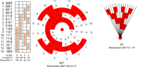
60 degree limit; 16 segments.
- Create a cylinder with 16x6 = 96 vertices; Radius 35; Depth 3.
- Edit mode; extrude radially; scale s using the following numbers (which makes the difference of the radii the same). The data is found on File:Gracode percentages.ods. The difference
| Radii | Subtraction (d=0.825) | Coeffiecient |
|---|---|---|
| Rmax | 7 | |
| R | 6.6 | 0.943 |
| r4 | 5.775 | 0.875 |
| r3 | 4.95 | 0.857 |
| r2 | 4.125 | 0.8333 |
| r1 | 3.3 | 0.8 |
- Make the cylindrical object which is to be attached to the axis. The angle is 100 deg.
- Interesting but not working method: Cube; Hole; Simple Deform; Array
The blend file: File:Gray disc.zip
Sizes
- Diameter of the axis: 25 mm
- Width: 10 cm
- Length: 7 cm (4.5 cm)
- Height: Less than 26 mm
- Diameter of the LDR is 0.51 mm
Four + two (4+2) radii.
- 7 / 6 = 1.1 cm
Steering
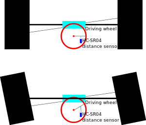


The angles needed are:
The motion of steering is restricted, thus the angle need to be measured. Two easy options:
- Use distance sensor (HC-SR04), or
- Use rotary encoder (single or multi track gray code)
Add the limit sensors to both.
Distance sensor HC-SR04
- Dependent on ambient temperature.
- Ping rarely so that no echoes.
- Tests on accuracy
Gray code
- In a gray code the bit distance between two consecutive words is exactly one (mono-difference).
- Accuracy:
- Absolute Position Coding Method for Angular Sensor—Single-Track Gray Codes
- The Structure of Single-Track Gray Codes
- Finding Single Track Gray Codes with SAT
Include the most significant bit (varies most) to outer circle.
Mechanics.
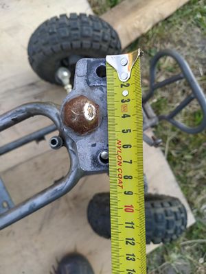
Python code
Python code to generate the gray code image
#
# Use sxiv to continously display the image
#
#

import drawsvg as draw
import math as math

def outline(r1, width, t1, t2):
    #Use degrees
    pi = 3.14159
    r2 = r1 + width
    d.append(draw.ArcLine(0, 0, r1, t1, t2,
            stroke='black', stroke_width=1, fill='none', fill_opacity=0))
    d.append(draw.ArcLine(0, 0, r2, t1, t2,
            stroke='black', stroke_width=1, fill='none', fill_opacity=0))

    #Convert to rads
    t1 = -t1*2*pi/360
    t2 = -t2*2*pi/360
    d.append(draw.Lines( r1*math.cos(t1), r1*math.sin(t1),
                        r2*math.cos(t1), r2*math.sin(t1),
                        close=False, fill='none', stroke='black'))
    d.append(draw.Lines( r1*math.cos(t2), r1*math.sin(t2),
                        r2*math.cos(t2), r2*math.sin(t2),
                        close=False, fill='none', stroke='black'))


maxAngle = 60

# Draw multiple circular arcs
width = 4          # mm
diff = 10          #
diff_center = 10   #Extra difference from the center hole
radius_center = 20 #mm

d = draw.Drawing(400, 400, origin=( -2 -radius_center, -400 +1 + radius_center))


#Draw the center hole
d.append(draw.ArcLine(0, 0, radius_center, 0, 360,
        fill='nore', stroke='black', fill_opacity=0))


#
# 1st row
#
period = 2 #(one black strip, one white strip)
phaseshift = 0
r1 = radius_center + diff_center + diff
t1 = 0
t2 = maxAngle/period
outline(r1, width, t1, t2)

#
# 2nd row
#
period = 2 #(one black strip, one white strip)
phaseshift = maxAngle/(2*period)  ##90 degrees
r1 = r1 + width + diff
t1 = phaseshift
t2 = maxAngle/period + phaseshift
outline(r1, width, t1, t2)

#
# 3rd row
#
period = 4 #(one black strip, one white strip)
phaseshift = maxAngle/(2*period)
r1 = r1 + width + diff
for i in range(0, 4, 2):
        phaseshift = maxAngle/(2*period) + i*maxAngle/(period)
        t1 = phaseshift
        t2 = maxAngle/period + phaseshift
        outline(r1, width, t1, t2)

#
# 4th row;
#
period = 8 #(one black strip, one white strip)
r1 = r1 + width + diff
for i in range(0, 8, 2):
        phaseshift = maxAngle/(2*period)+i*maxAngle/(period)
        t1 = phaseshift
        t2 = maxAngle/period + phaseshift
        outline(r1, width, t1, t2)

#
# Print it
#

d.set_pixel_scale(2)  # Set number of pixels per geometry unit
#d.set_render_size(400, 200)  # Alternative to set_pixel_scale
d.save_svg('gray.svg')
d.save_png('gray.png')

# Display in Jupyter notebook
#d.rasterize()  # Display as PNG
d  # Display as SVG

print( 'Total width: ', r1 + width, ' mm' )
Borderline only
Wheels and tires
Using an old kids ATV; 3" wheels; too small for pushing the snow, but perhaps enough for the first project.
Cheap axis:
- 125cc 835 mm, 55.90€: https://www.tuontitukku.fi/pienkone-vene-ja-varaosa/monkija-125cc-taka-aksila-835-mm-taka-aksila-monkijaan-83-5-cm/p/6419773800559/
- Takanapa 4x110 Mikilon Pentora 125cc; 32.90€: https://www.tuontitukku.fi/pienkone-vene-ja-varaosa/takanapa-4x110-mikilon-pentora-125cc-taka-akselille-jossa-19-os-20mm-boori/p/9977000025276/
Ulkohalkaisija täynnä noin 36cm (6")
- https://www.tuontitukku.fi/pienkone-vene-ja-varaosa/monkijan-rengas-vanteella-145-70-6-taka-eturengas-145-70-6-vanteella/p/6419773657219/
- https://www.tuontitukku.fi/pienkone-vene-ja-varaosa/monkija-rengas-vanne-vasen-7-lasten-monkijan-rengas-vanteella/p/6438471012071-s/
Current
Heat Dissipation
Motor
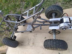
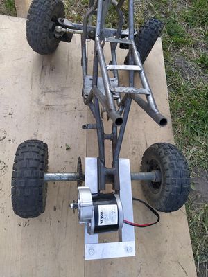
Motor Bed plan: keep is as simple as possible. Note that no welding machine, and other metal tools are scarce.
Torque, Speed, Duty Cycle
The gear is standard 410-9T bicycle chain (9 teeth). Thus, the gears from bicycles will be used for steering and driving. The wheel diameter is 3" (18 cm?), and the front gear is 9 spokes and the maximum rpm is 300. Thus, we have for the back gear
410 Roller Chain Dimension (see https://www.nitrochain.com/410-non-standard-roller-chain-10ft)
- Pitch 12.7 mm (1/2")
- Inner width 3.175 mm (1/8")
- Roller diameter 7.747 mm (0.305")
- Overall width 9.271 mm (0.365")
- Pin diameter 3.6068 mm (0.142")
- Link plate height 9.906 mm (0.390")
Vevor 24V 350W Nennstrom: 18,4A Brushed Permanentmagnetmotor Gear Reduction Packungsgröße: 22 x 19 x 17 cm (8,66 x 7,48 x 6,69 Zoll) Bruttogewicht: 3,05 kg
Chain
9 Zahnrad für Kette Nr. 410, Teilung 12,7 mm. Besonders gut für Heimwerker geeignet, da der Antrieb mit Standard-Fahrradketten (1/2 Zoll Teilung) kompatibel ist.
Shimano: 114L or 116L depicts the number of links, length, of the chain.
Chains are identified by the number of rear sprockets they can support, anywhere from 3 (why not 1?) to 13. The following list enables measuring a chain of unknown origin to determine its suitability.
- 10 speed – 6.0 to 7.0 mm (1⁄4 to 9⁄32 in) (Shimano, Campagnolo)
- 10 speed (Narrow) – 5.88 mm (7⁄32 in) (Campagnolo, KMC)
- 10 speed (Narrow, Direction) – 5.88 mm (7⁄32 in) (Shimano CN-5700, CN-6700, CN-7900)
Chains come in 3⁄32 in (2.4 mm), 1⁄8 in (3.2 mm), 5⁄32 in (4.0 mm), or 3⁄16 in (4.8 mm) roller widths, the internal width between the inner plates.
Chain widths
- 3⁄32 in (2.4 mm) chains are generally used on bikes with derailleurs such as racing, touring, and mountain bikes.[17] (Fixed sprockets and freewheels are also available in 3⁄32 in (2.4 mm) widths, so fixed-gear and single-speed bikes can be set up to use the narrower and lighter 3⁄32 in (2.4 mm) chains.)
- 1⁄8 in (3.2 mm) chains are typically used on bikes with a single rear sprocket: those with coaster brakes, hub gears, fixed gears such as track bicycles, or BMX bikes.
- 5⁄32 in (4.0 mm) chains are used on cargo bikes and tricycles.
Shimano cn-nx10 1s suits.
Motor Speed Controller BTS7960
We use BTS7960 based speed controller IBT-2 with max 43 Amps current. The datasheet is available at https://electropeak.com/learn/download/bts7960-43a-motor-driver-datasheet/
Example code from Electropeak or Hessmer
Pins
- VCC: 5V
- GND: Ground
- IS-R: Input signal for detecting high current – Straight rotation
- IS-L: Input signal for detecting high current – Inverse rotation
- EN-R: Output Signal for controlling motor direction – Straight rotation
- EN-L: Output Signal for controlling motor direction – Inverse rotation
- WM-R: PWM Signal for controlling motor speed – Straight rotation
- PWM-L: PWM Signal for controlling motor speed – Inverse rotation
Motor pins (High current):
- M+: Motor Positive; M-: Motor negative
- B+: Battery positive; * B-: Battery negative
Some instructions:
- https://www.homemade-circuits.com/dc-motor-speed-controller-circuits/
- https://howtomechatronics.com/tutorials/arduino/arduino-dc-motor-control-tutorial-l298n-pwm-h-bridge/
- https://howtomechatronics.com/tutorials/arduino/arduino-dc-motor-control-tutorial-l298n-pwm-h-bridge/
Extra things and older thoughs.
Use PWM. Feedback? Arduino L298N H-bridge.
Arduino pwm motor controller 300W 36V 20Amps
- https://www.pololu.com/product/755
- https://www.infineon.com/cms/en/product/evaluation-boards/bldc-shield_ifx007t/
- https://www.infineon.com/cms/en/product/evaluation-boards/kit_xmc47_relax_5v_ad_v1/
- https://www.canakit.com/50a-dc-pwm-motor-speed-controller.html
https://electropeak.com/learn/interfacing-bts7960-43a-high-power-motor-driver-module-with-arduino/
High power dc motor speed controller
- https://www.ebay.de/itm/255283289430?hash=item3b7011dd56:g:ooAAAOSwhexb6eW9&amdata=enc%3AAQAIAAAA4Gjfo%2FMILLwl3G9ygIqNAj7fpl%2FtigoAQMba%2FwqTqxj%2F4nqjin1d6Re7Jqa2XBzZBTYTsTZEUjiXEhH%2BpvJd1RaWoR5%2FsWhgtcwpXnTrpL1Y5wDPHZ1wJJTmdK4mb4LOQLw%2BmqT%2B9tcOBX%2BAwD37WZcEfTk3P5B6boz%2BRV7G1fj3KiqeZ%2B0ZA98o9mIFBOG2E6fxDo9K3cQN2u5M53jQ7PrP6%2BjtJTGNnfCQA0tuOE8V8bAfFmBRCnPAFt001aTDSAUCuyxzZNQK%2FaKJMdzbLnmLjxgPMQmkSpSDCFQrBg8D%7Ctkp%3ABFBM6Ie9uvph
- Amazon: Songhe BTS7960 43A, HiLetgoBTS7960 43A, Melife PWM 10-50V 60A,
- https://www.ebay.de/itm/123021644824?hash=item1ca4a95418:g:nbkAAOSwFwlgA~qm&amdata=enc%3AAQAIAAAA4D2ya%2FD4v6plC%2B8Wi7%2BlXiqyFvx9ZVmTFiGrhSZCNY2YnjdXjYQSdBGKApiC33DWt5chAE5RKlktpUjFvfAH7zshCx42W8yONOQ4zchZuo1246qn5qB8HmRBhVVuQ4urPQKY5239P%2FA%2BODko%2BEp8V0A2%2FuEAhTO2Dxs5GGNBIJL45pGyQFEMNEa8NpisE0ebKnTokdhtuJVPQNap6U0DW1jeEwasXUUanOoWC0uDn%2Bt2gC3ulFIBbXn1epQw3wCnTR1iOv%2BRR%2Fz5KjKpYRsaZfmprbV7gONgMIgdZ3QgdJ%2B6%7Ctkp%3ABk9SR7rT4rf6YQ
- https://www.ebay.de/itm/165676940912?hash=item26931d7e70:g:q8YAAOSwVM1jIqNq&amdata=enc%3AAQAIAAAA4CKa5nRcyz0RlXcN3Iw7mhcTalyBSBfC33bdLn08wqjCcgaPgKgjMgdkmbwdwGTC6QibwZ7WjVqyWysp7Uh97reXnrw5Srml4CJ9O%2FyBC8wqga6cohaq7tBAZOgFx9G1PP9PzZ7QEYWiGCiR4%2F55MdLP8kI%2B4gynCWyknKAlshev5BExzvKvazuC0SGQQEqT6WFZy6m%2Bp1jw7jwGlg8I8dFZ0O5s%2Fizj6E7DzlotaLFb8OiyJKRzpuPZSo2vpAM2Q5831W6kODRgLCo0N0QlmaU5HUxUq4AEXCiPrsit0W7R%7Ctkp%3ABk9SR7zT4rf6YQ
- MD25HV https://makermotor.com/pn00218-cyt13-25amp-7v-58v-high-voltage-dc-motor-driver-speed-controller-md25hv/
Radio controller
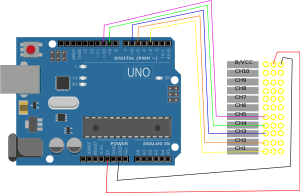
We chose Flysky FS-i6X RC Radio Sender & FS-IA10B Set 10-Kanal 2,4 GHz AFHDS unit to send and receive data.
// https://medium.com/@werneckpaiva/how-to-read-rc-receiver-signal-with-arduino-54e0447f6c3f
#define CH1 3
#define CH2 5
#define CH3 6
#define CH4 9
#define CH5 10

// Read the number of a given channel and convert to the range provided.
// If the channel is off, return the default value
int readChannel(int channelInput, int minLimit, int maxLimit, int defaultValue){
  int ch = pulseIn(channelInput, HIGH, 30000);
  if (ch < 100) return defaultValue;
  return map(ch, 1000, 2000, minLimit, maxLimit);
}

// Red the channel and return a boolean value
bool redSwitch(byte channelInput, bool defaultValue){
  int intDefaultValue = (defaultValue)? 100: 0;
  int ch = readChannel(channelInput, 0, 100, intDefaultValue);
  return (ch > 50);
}

void setup(){
  Serial.begin(115200);
  pinMode(CH1, INPUT);
  pinMode(CH2, INPUT);
  pinMode(CH3, INPUT);
  pinMode(CH4, INPUT);
  pinMode(CH5, INPUT);
}

int ch1Value, ch2Value, ch3Value, ch4Value;
bool ch5Value;

void loop() {
  ch1Value = readChannel(CH1, -100, 100, 0);
  ch2Value = readChannel(CH2, -100, 100, 0);
  ch3Value = readChannel(CH3, -100, 100, -100);
  ch4Value = readChannel(CH4, -100, 100, 0);
  ch5Value = redSwitch(CH5, false);

  Serial.print("Ch1: ");
  Serial.print(ch1Value);
  Serial.print(" Ch2: ");
  Serial.print(ch2Value);
  Serial.print(" Ch3: ");
  Serial.print(ch3Value);
  Serial.print(" Ch4: ");
  Serial.print(ch4Value);
  Serial.print(" Ch5: ");
  Serial.println(ch5Value);
  delay(500);
}
Gear ratios
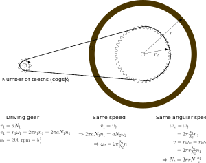
Gear ratio
Cutted parts and files
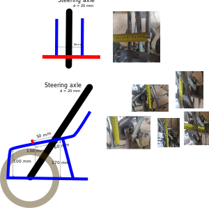
Inkscape's G Code generator, or use JsCut
Rotation detector. Plasma cutter.
- Center hole: diameter 20 mm.
- Width: 14 cm.
Steering gear plate:
- Just two holes
- Distance between hokes 56 mm.
Driving gear plate
- Just some holes.
Cutting the grass
RPM, tip speed,
Tip speed. The faster the blades move the sharper, more define the cut... impact energy
- Anything over 90 m/s is fine.
- 84 m/s (16,500 fpm) blade tip speed
- WB mfg are up near 86 m/s or 91 m/s (17k or 18k fpm). Husqvarna WB with a tip speed of 81 m/s (15.9k).
- blade tip speed with 94 m/s
- the design of the deck.
Blades available from a shop
- 32cm
- 33cm
- 38cm veitsiterä
- 42cm
- 43cm veitsiterä (bio)
- 46cm veitsiterä (akkukäyttöinen)
- 48cm veitsiterä (bio, akku)
- 49cm
- 50cm
- 51cm
- 53cm (myös 2x, eli 107 cm) 42"
- 56cm (bioleikkaava)
For example (at 97 m/s blade speed, 3.5 m/s ground speed, running single blades--so you get two "cuts" per revolution):
- 30.5cm blade: 6048 rpm (!), 1.8 cm of ground travel between cuts (in/cut)
- 42cm blade: 4398 rpm, 2.5 cm
- 46cm blade: 4032 rpm, 2.7 cm
- 53cm blade: 3455, 3 cm
- 61cm blade: 3023, 3.5 cm
The blade should spin at approximately 3000 RPM (revolutions per minute) to cut grass efficiently. ANSI standards: the tip of the blade should spin at a speed no greater than 97 m/s.
Trimmer mower or field and brush mower for a very long grass


